
Hello
I purchased four 24V12s for a project
I finally got around to using them and I am a bit surprised. No output
Previous email discussions on use of Solenoids in place of motors as per Texas Instrument slva 460 seemed feasible
oddly, I get full uncontrolled power using configuration VM and no power using GND configuration. I checked my RC input with an oscilloscope and the proportional performance is spot on as the control moves. I checked for Voltage and there is zero. I tried a different card, same result so its not a problem induced by the solenoids
Hello.
I revisited our email conversation and it sounds like you are working with our Simple High-Power Motor Controller 24v12 and that you are referring to this Texas Instruments document. Did you perform any configuration of the SMC using the Simple Motor Control Center software and, if so, how do you have your input configured? Can you post the settings file from your SMC (inside the Simple Motor Control Center, click File >> Save Settings File…)? Are you testing the output voltage with your oscilloscope? What output points are you checking? Does the output change if no solenoid is attached? Where do you have the solenoid connected on the SMC in the “GND” and “VM” configurations you mentioned?
-Nathan
Thank you for revisiting the chain and including links for the forum. I did
not do any configuration of the 24v12 Simple Motor Controller as I assumed
it should work immediately for test purposes.
the error light stays lit and the yellow led blinks about one time a
second. I was trying to figure out what the error was and it appears to be
a communication error but I cant solve it yet
I was testing for voltage output at OutA and OutB with standard Volt Ohm
meters.It reads OV. Since I use two 12V lead acid, my voltage is 25.6V
across the terminals. I have used the BEC jumper to supply 5V to the RC
receiver on both cards tested. It does not matter if I use the RC receiver
battery pack or the BEC jumper, the result is the same. The board appears
to work, I suspect that the RC connection is not talking
I am quite excited about this application once the bugs are out.
The SMCs are configured for Serial/USB communication by default, so you will need to use the Simple Motor Control Center to configure them for RC input. The “Configuring Your Motor Controller” section of the user’s guide goes over this in detail, but let me know if you have any questions or anything in there is unclear.
-Nathan

Can you post pictures that show how you have the board connected? How are the Analog 1 and Analog 2 input channels configured? Instead of taking a picture of those configurations, you can post the entire settings file for your SMC, which will include information about how those channels are configured. To do that, open up the Simple Motor Control Center and click File > Save Settings File…
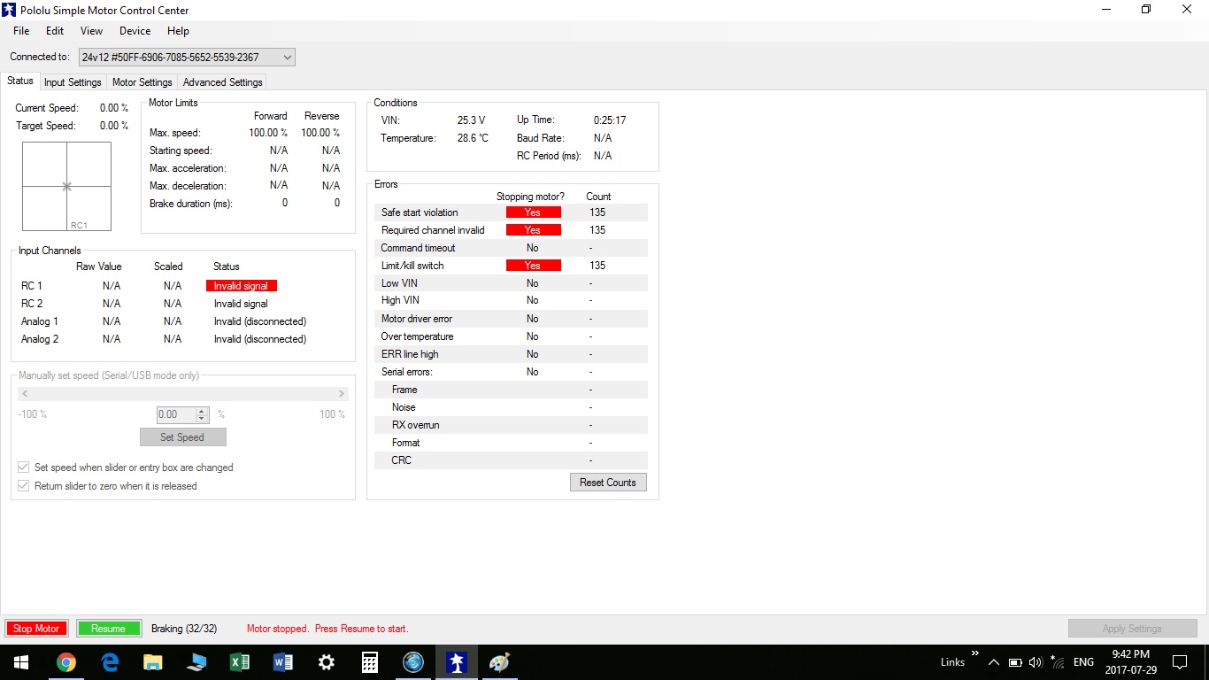
Also, does the “Invalid signal” status on RC 1 ever go away if you vary your input signal (by moving the joystick on your RC transmitter)?
-Nathan
the invalid signal never goes away and the analog channels are not configured
I thought the analog and rc would not work at the same time so will go back and check this
moving the joystick changes nothing regardless of which output or input combination I try.
the oscilloscope indicates that rc controller works on all channels, it just does not process
smc_settings.txt (2.89 KB)

Your settings file looks OK. In your picture, it is difficult to tell for certain, but it looks like you might have your RC channel plugged into the RC2 input (instead of RC1) or that you might not have the GND connected between your RC receiver and the SMC. Also, is the red wire the signal wire on that cable?
-Nathan
If there was no ground to the receiver, I would have no RC signal. I can read an RC signal and prove it varies. I can probe the signal pin and get the variance. The signal wire is red but wire color has nothing to do with it.
I have tried RC1 and 2 with no change. I get a change in the SMC if I use analog 1 and manually vary it.
Why no RC
it should be read continuously if I understand the manual.
It’s gotta be simple whatever it is.
Sent from my BlackBerry 10 smartphone on the Bell network.
Where in the circuit did you use the oscilloscope to measure the RC signal? Also, where did you ground the probe? Could you post a picture of the signal your RC receiver is sending?
-Nathan