New to Raspberry and Stepper Motor Controllers

Hello,

I’m new to Raspberry Pi, or any modern micro and not a programmer either. I’m an old EE that designs chips (RF & Analog). I do understand general hardware/motors fairly well, but not so good with software/controllers. Would like to get a Raspberry Pi system up and running and learn to do some things that would be useful for my interest which is photographing the chips I’ve and others have designed. Macs are the main computers I have access to, and prefer to stay away from PCs if possible. I’ve ordered a Raspberry Pi development kit and add on stepper motor control PCB from another source before finding this site. From what I’ve seen here at Pololu, this seems aligned little closer to what my interests are in setting up a stepper motor control system, especially with the Tic stepper controllers boards and the DRV8825, and all the folks discussions.

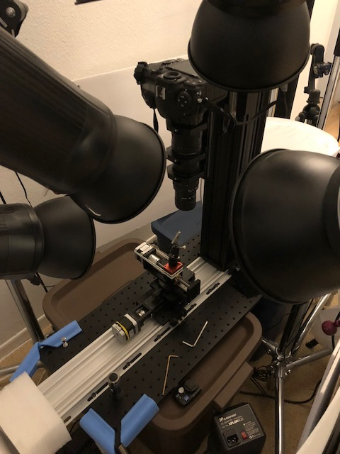
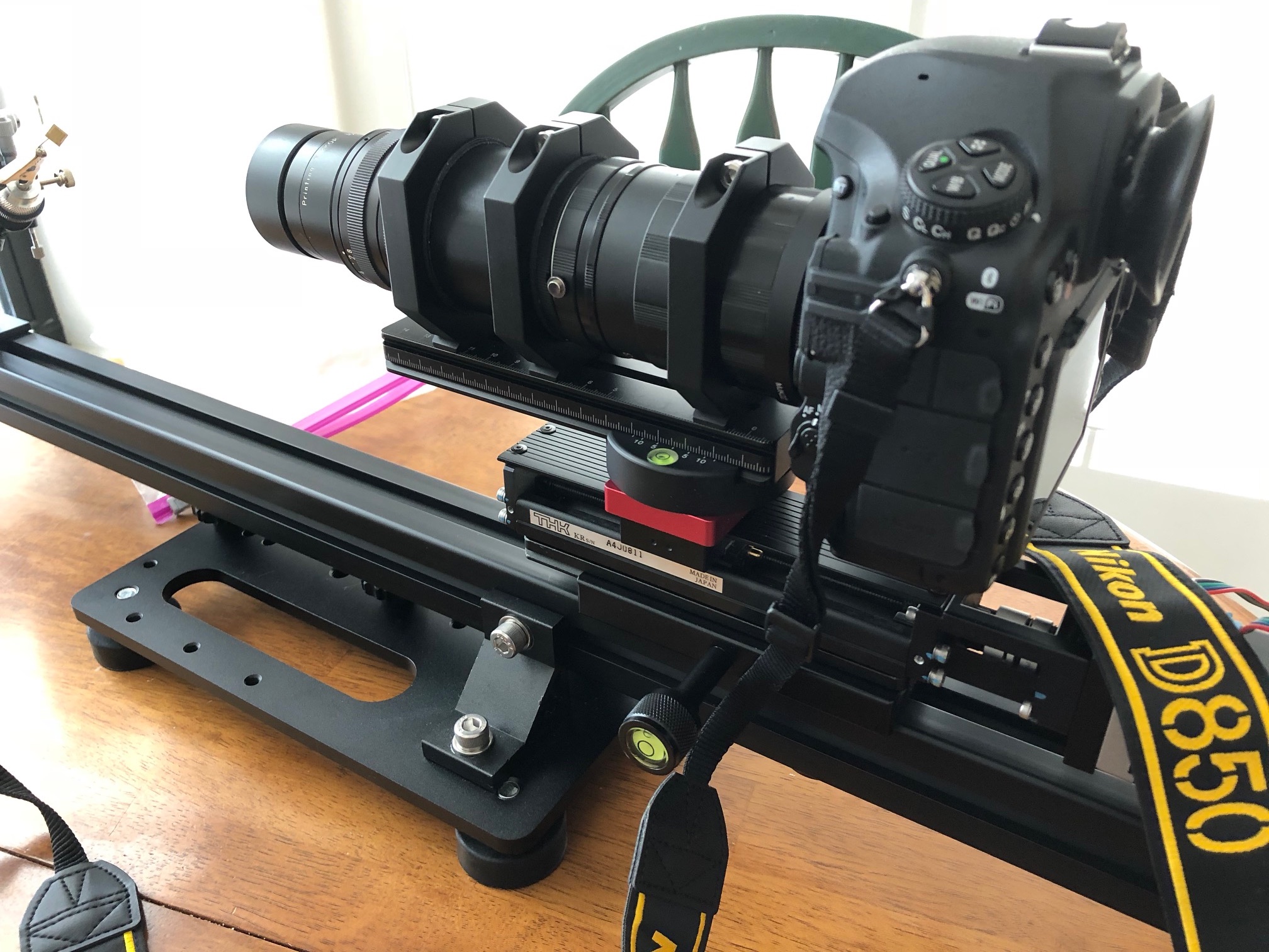
One area of particular interest is macro photographing chips using focus stacking where a linear stage is driven by a stepper motor controlled by some computer. Focus stacking helps with the shallow depth of field in macro, and popular with insect macro-photography. The stage is usually driven by a NEMA 17 stepper motor which turns a screw thread moving the stage which holds the camera & lens, so focus stacking is achieved by moving the camera/lens rather than using the lens focus ring. I have a few of these setups now that use various dedicated computer/controllers from various vendors specializing in this and some that require an additional computer (PC, Mac, iPad, iPhone) for setting up the stacking parameters and running the system. These all work well for their intended purpose, running a single stacking session.

What I would like do is run a focus stacking session, then move the subject to a new location, run another stacking session and move the subject to another location and repeat. This will produce a panorama type macro where the single stacking session only covers a portion of the subject, resulting in multiple stacking sessions covering there entire subject. These individual stacking sessions will the focus stacked with dedicated software (Zerene for example), then the stacked image renderings “stitched” into a final macro-panoramic image in Photoshop or other dedicated software. I’ve done this successfully by hand few times (moving the subject) to realize that a dedicated system might be useful. Some commercial dedicated systems are available but most are out of my price range and some only work with PCs (I only have Macs).

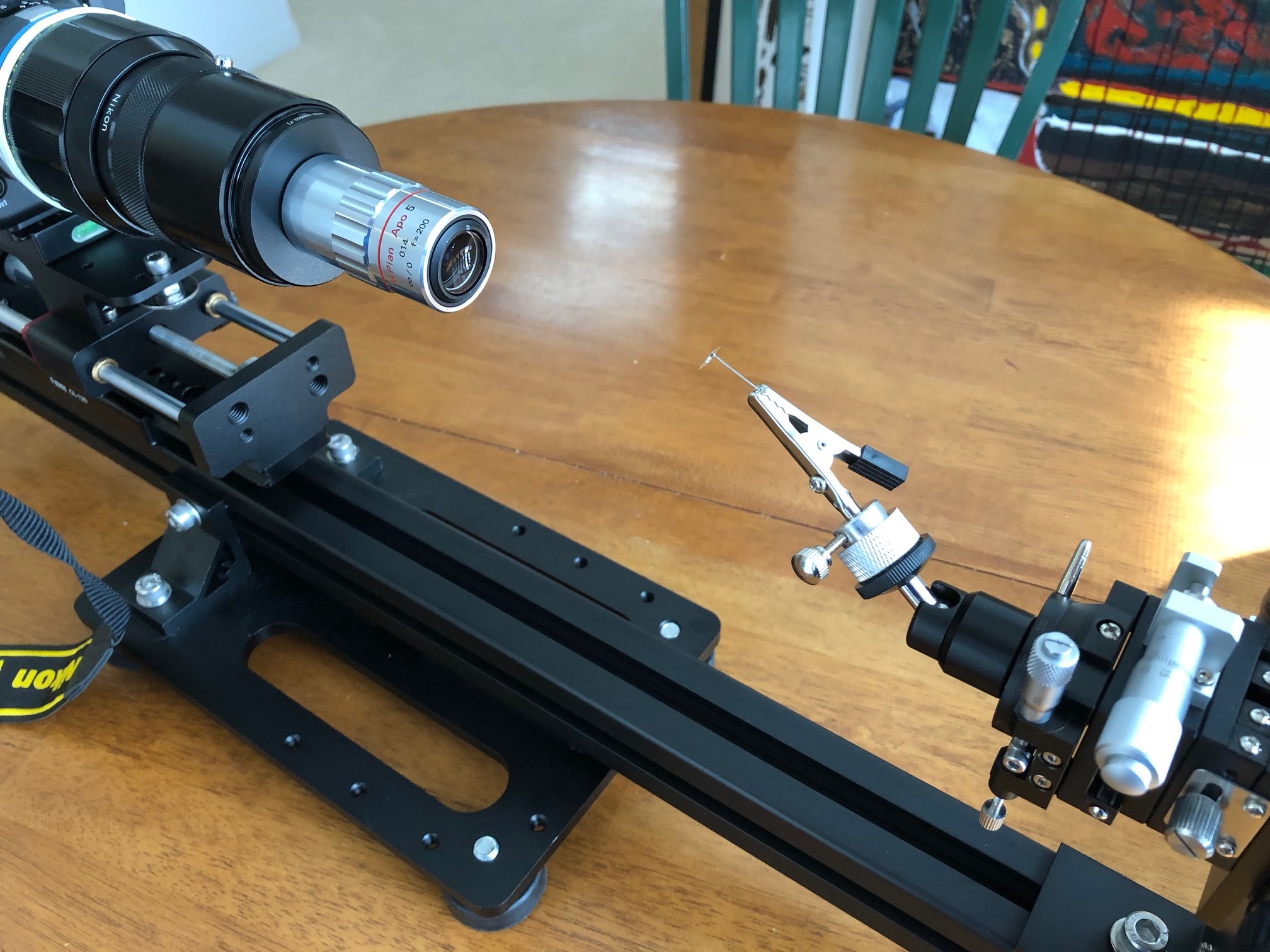
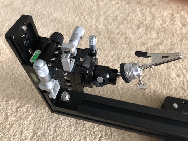
So what I need to do is control the Vertical Z stage (stepper motor) which will hold the camera/lens setup for focus stacking, then move the subject which will be mounted to an XY stage orthogonal to the Z axis on the Horizontal base with a separate stepper motor for X and one for Y. The subject will be moved in X and Y directions, while the Z direction will be for focus stacking.

For setting up the overall stack and panorama session, I’ll need to define the stacking (Z) beginning, stack depth or end, number of stacks or step size, stepper movement (micro stepping, speed, backlash), wait times (for vibration settling), trigger camera & delayed trigger strobe/flash. Then will require the X movement and Y movement parameters. The X and Y movements don’t need the precision of the Z axis movements and are relatively coarse (many microns to a few mm), however the Z axis requires precise movements down to a ~ 1 micron. I already got linear rails (surplus THK KR20 for example) with 1mm thread pitch and 400 step NEMA 17 motors, thus producing 2.5 micron steps without micro-stepping. I have other rails that I can use for the less precise X and Y stages, these also have 400 step motors.

For an example, the subject might be a chip with 20mm by 14mm dimensions and the lens system has a field of view of ~6mm, but the chip is tilted to give a somewhat “3D” look and has a depth of ~2mm. The lens has a magnification of 5X and a depth of field (in focus area) of only 0.05mm. With overlap this will require 4 separate X stacking sessions and 3 separate Y stacking sessions, or 12 in total, and each Z stacking session will require about 50 separate images. Overall ~600 separate images will be collected. I’ve already done this a few times requiring ~6000 images by hand (moving the X & Y subject positions) and it’s quite tedious indeed!!

Anyway, I would like to start with a Raspberry Pi 3 system that will be eventually stand alone without the requirement for another computer (although initially another computer to sort things out and a Mac development computer is OK), can handle this effort described, has a display and possibly a means to enter data parameters (touch screen or remote keypad-board). Note the Raspberry Pi does not need to collect any image data, just control the stacking sessions Z axis (stepper motor) focus rail and the XY subject positioning rails (stepper motors), and allow setting up the various stacking session parameters.

I understand that Python is probably a good start. I’ve looked at some stepper motor tutorials and the code and have a general idea of how to directly control the motors (like turning ON, then OFF the I/O pins which drive the controller H bridge and cause the motor to make 1 step), but the detail code initial setup and such for communicating and loading the various libraries is still a little daunting, but I’m making some progress!!

Thanks for the time reading this initial long post and any help/guidance/assistance/recommendations are greatly appreciated.

Best,

Mike

Hello, Mike.

The Tic could be useful for you if you want to control the motor by calling a command line utility (which we call ticcmd) instead of toggling a couple of I/O pins per motor using stepper motor drivers. Python is probably the most straight forward way to work with I/O pins on the Raspberry Pi and it should be possible to call the ticcmd utility from Python, but you could also use something like a Bash script if that makes your project easier. Also, offloading motion control things like acceleration to the Tic would probably simplify your code a little; you would probably want to integrate that into your code for a regular motor driver. You can find more about the control methods for the Tic in its user’s guide, which is linked to on the “Resources” tab of its product page.

The microstepping features of current limiting drivers like the DRV8825 are generally intended to smooth motion, but they do allow finer control of movement in some systems. You should be aware that the DRV8825 will sometimes skip microsteps with certain low inductance/ low coil voltage stepper motors, though in your system, it sounds like skipped microsteps might only be an issue for your Z axis. If you post a datasheet for your motors, I can see if they are likely to have problems.

-Nathan

Nathan,

Thanks for the reply and information. Toggling a couple I/O pins seems a little more straight forward to me than the command line approach, especially since my software knowledge is limited, thus my note about the DVR8825. I am slowly becoming more knowledgeable about software though, and begging to appreciate this approach. What is a Bash script?

The motors I have don’t have spec sheets but came with a kit to modify a THK KR20 linear rail, or with another rail. This kit is intended (as are the rails) to support micro-stepping capability since the available controllers allow for this. One controller utilizes an ON-Semi controller that allows down to 1/128 micro-steps, and the other controller allows 1/8 micro stepping, so believe the motors (these are both 200 and 400 step motors) should work properly with micro-stepping. The THK KR20 linear rails have 1mm thread pitch screws, so I get 2.5 micron steps without micro-stepping, and really don’t need resolution better than 2.5/4 microns. When I use the rails now I usually don’t step with anything other than integer values of 2.5 microns so as not to engage micro-stepping to avoid any possible additional induced vibration by micro-stepping. At the sub-micron image levels I’m working with precision lenses and high resolution sensors any source of vibration reduces image quality, so careful to watch out for these potential sources.

Here’s the vertical 3 axis setup under construction for this project. It’s based upon a Thor Labs optical base and 95mm precision optical stage. You can see the two XY axis rails attached to the base (rubber bands are to eliminate backlash in one of the non-THK linear rails, the THK rails have no measurable backlash). The vertical Z axis holds the focus rail and camera/lens (one of the used lenses).

Here’s what the setup looks (older version) like when single axis focus stacked operated horizontally.

Thanks so much for the reply and help. Sorry for being so naive about the software and such, but it’s been 40 years since I did any programming (original Apple II 6502).

Best,

Mike

Nathan,

Here’s a few more images that may help show what I’m working with.

This is a new single axis somewhat portable vertical/horizontal system. You can see the THK KR-20 focus rails, Nikon camera (I use D800E, D500 and D850) and custom lenses.

Note the micrometer subject positioning. This is what the two additional stepper motor rails are replacing for a completely automated stacking and panoramic stitching setup…hopefully.

IMG_1358

I’m sure the coding would be trivial for you, but is somewhat daunting for me!! But I’m learning and making some progress, so this is encouraging!!

Anyway, hope this helps show what I’m trying to do. Here’s a link to show some of my prior work that I can show (most is proprietary though).

http://img.gg/yZNjmZ2

Best,

Mike

That looks like an interesting project. Thanks for sharing it here.

Bash is the command line interface for most Linux distributions.

Electrically, bipolar stepper motors are just two coils of wire. Full steps occur when the direction of current in either of the coils occurs and microstepping controls the current through the coils so that the magnetic field the rotor wants to align with is midway between full steps. This current control uses a PWM algorithm that applies the driver’s input voltage across the coil at a variable duty cycle. The algorithm the DRV8825 IC uses to control current can have trouble with some common NEMA 17 size motors that have a combination of low coil inductance (below around 10mH), low coil voltage (below 2 or 3V at the rated current) and high rated coil current (above about 1.2A).

If your kit uses motors like that and you need positional accuracy around 1/4 microstepping, we recommend an A4988 driver (with 1/16th microstepping) or mp6500 driver (with 1/8th microstepping) over the DRV8825 boards. If you need 1/32 microstepping or your motors require more current than the A4988 and MP6500 drivers can provide, our TB67S2x9FTG stepper motor driver carriers have a more capable current control algorithm than the DRV8825 and should work better with motors like those I mentioned above. We also have a stepper driver carrier based on ON Semiconductor’s AMIS-30543 IC that has 1/128 microstepping (and a pretty capable current control algorithm), but the downside to this driver is that in addition to the step and direction pins required by all of the other drivers I mentioned, the driver also requires some initialization over an SPI interface before it can be used to drive a motor. We have a library for doing this using the Arduino platform (a platform to abstract and simplify programming some specific microcontrollers) , but you would need to port the code or otherwise accomplish the same functionality using the Raspberry Pi.

This Hackaday article has some nice quantitative results that illustrate the limits of microstepping accuracy and there is some theory about microstepping and torque in this application note.

-Nathan

Nathan,

Thanks for the notes and information. I was leaning towards the DVR8825, but after looking at the test results from the article I’m going to order the A4988 Driver boards.

I did Goggle Bash and took a quick look, I’ll need to spend more time on this.

Best,

Mike

Hi Nathan,

I’ve received the A4988 boards and other stuff from Pololu, thanks a bunch!! So don’t feel so bad about asking for help now that I’ve spent some $ :grinning:

As mentioned I picked your A4988 boards over the DVR8825 because of the performance during micro-stepping.

After assembling the Raspberry Pi 3B and A4988 board (setting the current limit also) with a couple stepper I have (only one at a time) and kludging up some code from various places I’ve actually got the motor control working nicely.

I’ve moved to controlling the A4988 “Step” pin with the Raspberry Hardware PWM pin 12 for a smoother control. Now I need to figure out how to determine the relative position of the linear rail stage, I’m using (THK KR20 with a 1mm thread pitch and 400 step NEMA 17 motor). I figured that somehow the step count on pin 12 of the Raspberry Pi output can be recorded, and between the previous position and the direction I should be able to figure out the new position.

Any pointers or ideas are greatly appreciated.

Best,

Yes, it should be straight forward for your code to track how many times it has driven the STEP pin high to determine its position relative to where it was when the code launched. For an absolute position, it is common to drive the carriage in one direction until a portion of the carriage bumps into a switch (connected to a separate I/O pin that is also monitored by the code). 3D printers often use snap action switches placed perpendicular to the direction of travel to sense the home position, which generally seems to be repeatable enough for the 0.1mm accuracy typically required for that application. There are many other types of switches/sensors like hall effect sensors, inductive sensors, and opto-interrupter sensors that might be better options if a physical switch is not repeatable enough.

-Nathan

Nathan,

Thanks for the reply.

I’m using the code below to write to the A4988 step input;

pi.hardware_PWM(STEP, speed, 128)

“STEP” is defined as pin 12 on the Raspberry Pi B and is electrically connected to the A4988 step input, “speed” is the pulses per second and “128” sets the pulse output duty cycle to 50%.

I just don’t know how to count the pulses that are output by pin 12 to know how many steps were taken. Is there a way to do this, count the pulses from the hardware PWM pins? I’ve looked and couldn’t find anything

BTW your black A4988 boards ( I got 5) work very well!!

Your help is greatly appreciated,

Best,

Mike

Nathan,

If there is no reasonable way to count the hardware pin PWM pulse output, would the Tic 500 be useful for this application with the Raspberry Pi 3B? Is it difficult to convert the Adurino code library for use with the Raspberry Pi and get it to work over IIC and/or USB considering I’m a beginner?

Best,

Mike

I should clarify my statement about it being straight-forward to count the number of pulses sent to the step pin; that is using something like a for or while loop to toggle one of the GPIO pins high and low and using a function like time.sleep() to control how long to wait between each of the steps.The drawback to this approach compared to using hardware PWM is that it limits your maximum step rate and there can be some variability in the frequency with which the steps are executed (especially on a system with an operating system, where other processes running on the system could influence the timing of the code). Unfortunately, we are not aware of a way to accurately count pulses sent with hardware PWM. You might consider using a loop with the sleep() function if you have not already done so.

Alternatively, the Tic stepper motor controllers have a dedicated microcontroller on board and our firmware produces accurate step rates and numbers of steps. It can even do those things using uniform acceleration rates, which should help produce smoother movements. It is possible to control the Tic from a Raspberry Pi with either the USB or the I2C interface, which are explained in the Setting up USB control and Setting up I²C control sections of the Tic user’s guide. The Example I²C code for Linux in Python section has some code that is probably a better starting point for you than our Arduino library for I2C control and the Example code to run ticcmd in Python section shows how to call our ticcmd utility to control the Tic over USB.

-Nathan

Nathan,

Thanks. Guess I’ll give the Tic500 a try and see if I can get this working with USB or I2C interface. If I use USB can all 3 Tic500 be connected to a USB hub instead of using 3 of the Raspberry USB ports (know some USB stuff doesn’t like this)?

Your help is greatly appreciated,

Best,

Mike

We do not expect any specific problems using a USB hub.

-Nathan

Hi Nathan,

I’ve ordered 3 Tic500 which are in transit. In the meantime I’ve been getting prepared to test the boards when they arrive. I plan on using USB initially from the Raspberry 3B and/or my Mac Pro so I’ve downloaded the apps for each without issue.

I also want to try and use ticcmd from the Raspberry, but cant get the yam1 to work. I’ve followed the instructions carefully and uses pip but get the error messaged No module named yam1 from when yam1 is exercised in the example code at 12.3. I noted the mention of not using yam1 and just reading the Tic500 directly (since apparently it’s so easy), but not sure how to do this since no reference example is shown. Would this error result be expected since I have no Tic500 board connected?

I’m quickly getting the feeling I’m way over my head on trying to interface to the Tic500 with USB or I2C.

Any help is greatly appreciated,

Best,

Mike

It looks like you are typing out the number “1” rather than a lowercase letter L at the end of “yaml”, so if you are typing it that way into your Raspberry Pi, you should use the letter instead of the number. If that doesn’t solve the problem, could you let us know what is returned when you run the following command from the command prompt?

sudo apt-get install python-yaml python3-yaml

-Nathan

Nathan,

Thanks for spotting this, I’ll give it a try tonight when I get home. BTW I did get 3 of the Tic500 and had the stepper motor running under USB from the Raspberry Pi 3B, I’ll try the ticcmd line tonite also.

Best,

Mike

Hi Nathan,

Just got back to this effort and still get the error message “ImportError: No module named ‘yaml’. I’m running the copied code form 12.3 shown below.

# Uses ticcmd to send and receive data from the Tic over USB.
#
# NOTE: The Tic's control mode must be "Serial / I2C / USB".

require ``'open3'
require ``'yaml'

def ticcmd(*args)
``command = ``'ticcmd ' + args.join(``' '``)
``stdout, process_status = Open3.capture2(command)
``if !process_status.success?
``raise "Command failed with code #{process_status.exitstatus}: #{command}"
``end
``stdout
end

status = ``YAML``.load(ticcmd(``'-s'``, ``'--full'``))

position = status.fetch(``'Current position'``)
puts ``"Current position is #{position}."

new_target = position > ``0 ? -``200 : ``200
puts ``"Setting target position to #{new_target}."
ticcmd(``'--exit-safe-start'``, ``'--position'``, new_target)

I’ve copied the

sudo apt-get install python-yaml python3-yaml

and copied & tried

pip install pyyaml

I have the Tic500 connected with your USB cable to a Raspberry Pi 3B and the ticcmd write lines work, as does the ticks status read. I’ve also run the Ticgui and it works.

I really would like to get to doing some attempts at actual creating some software to directly control the Tic500 today. I’m thinking of using the Tic500 with USB (unless you think otherwise), I’ll eventually use all 3 Tic500s I have, but want to start out simple first. I’ll need to read actual motor position from the Tic500 (couldn’t find an example other than 12.3), also need to write things like goto this position at this speed and so on. If I use Python (or your recommendation) is there another reference besides 12.3? 12.3 seems so simple but I cant get it to work.

Thanks for the help.

Best,

Mike

Hi Nathan,

I was able to get the code to run using sudo python from a terminal but it won’t run from the “Run Module” from the python shell. I suspect this has something to do with the path to the paml module?

Thanks for the help,

Best,

Mike

I am glad you were able to get the code working. Normally you do not have to be root to use PyYAML; I am not sure what is wrong with your setup.

-Nathan

Nathan, others,

I’ve made some good progress and have the Tic500 working nicely with the Raspberry Pi3B with USB. Is there a way to defeat the timeout from the command line without having to use the ticgui?

I’ve developed some mods to the code from the Users Guide 12.3 as shown below for controlling the Tic500 from USB. I’m having a difficult time getting to the next step where I would like to be able to save the last Tic500 position into a variable and exit this routine. I want to eventually use this routine to move the motor to a position under various passed parameters and store the position to various variables, actually I’ll be doing this with 3 Tic500 and motors (Z, X&Y), but that’s further down the road. I’ve tried all sorts of things but cant get anything to work.

Thanks for the help and guidance,

Best,

Mike

Modified code from 12.3 Tic500 Users Guide.

# Uses ticcmd to send and receive data from the Tic over USB.
# Works with either Python 2 or Python 3.
#
# NOTE: The Tic's control mode must be "Serial / I2C / USB".
 
import subprocess
import yaml
 
def ticcmd(*args):
  return subprocess.check_output(['ticcmd'] + list(args))
 

status = yaml.load(ticcmd('-s', '--full')) # Get Tic500 data
position = status['Current position'] # Get inital position
print("Inital Position is {}.".format(position)) # Display inital position


try:


    while True:
               
        desiredposition = input ('Enter Desired Position ') # Enter desired position    
            
        print("Setting Target Position to {}.".format(desiredposition)) # Display desired position  
                     
        ticcmd ('--position', str(desiredposition)) # Write to Tic500 desired position


finally:
    ticcmd('--exit-safe-start')