OK, after searching for everything posted about the A4988 and reading for over 5 hours now, pooring over the FAQ’s on Pololu’s website, numerous Google searches and the datasheets for the A4988, I still cannot find the fix for my stepper not responding correctly. It’s just basically twitching erratically when powered up.
Yesterday it was semi working OK, but changing the delay after the “digitalWrite(stepPin, HIGH)” in the code below did nothing to change the rate of rotation. But when the values for “j” on the Serial Monitor window were below 10, it would rotate faster. Now I cannot get it to do anything but twitch erractically. I have been careful not to make or break connections with the power applied.
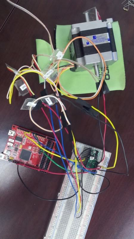
-I’m using an Anaheim Automation 8 wire bi-polar stepper that the sticker says is 1A/Phase
-Seeeduino Mega (ATMega1280 chip with Arduino interface) (I’ll just call it an Arduino for future reference)
-Pololu A4988 driver
-30V / 5A variable power supply
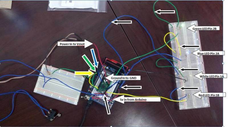
-I have the 5v input to power the A4988 hooked up to the Adruino and ground as well
-I’ve tried 8 to 28v into the Vmot with the cooresponding ground from the power supply hooked up
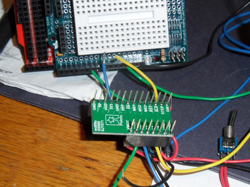
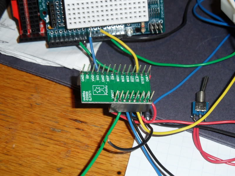
-SLEEP and RESET are jumped together, I’m reading 4.75v on these
-There’s nothing hooked up to the MS1, MS2 and MS3 so I should be running in full step mode
-I have adjusted the Ref voltage to .597v (initially) and then down to .37v with no change. This was measured from the Ref pin to the common Arduino/A4988 ground.
I have the motor hooked up in series configuration per the FAQ page diagram with the appropriate wires tied together, and this cooresponds with the connections given by the motor datasheet located here: http://www.anaheimautomation.com/manuals/stepper/L010164%20-%2023Y%20Series%20Spec%20Sheet.pdf
Note: I tried parallel as well with no change, I’m still working with it hooked up in series.
ENABLE, DIR and STEP are hooked up to the Arduino and I’m trying to use the following to get this sucker to run right…
#define stepPin 7
#define dirPin 6
#define enablePin 8
void setup()
{
pinMode(enablePin, OUTPUT);
digitalWrite(enablePin, HIGH);
Serial.begin(9600);
Serial.println("Starting stepper exerciser.");
pinMode(stepPin, OUTPUT);
pinMode(dirPin, OUTPUT);
}
void loop()
{
int j;
digitalWrite(enablePin, LOW);
delayMicroseconds(2);
digitalWrite(dirPin, HIGH);
for(j=0; j<=250; j++)
{
digitalWrite(stepPin, LOW);
delayMicroseconds(2);
digitalWrite(stepPin, HIGH);
delayMicroseconds(1000);
Serial.println(j);
}
for(j>250; j<=500; j++)
{
digitalWrite(dirPin, LOW);
digitalWrite(stepPin, LOW);
delayMicroseconds(2);
digitalWrite(stepPin, HIGH);
delayMicroseconds(1000);
Serial.println(j);
}
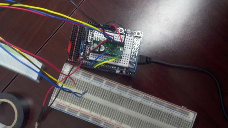
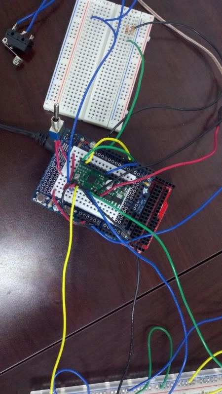
}Not sure if there’s enough detail to help, but here’s the settup:
Thanks in advance for any help!