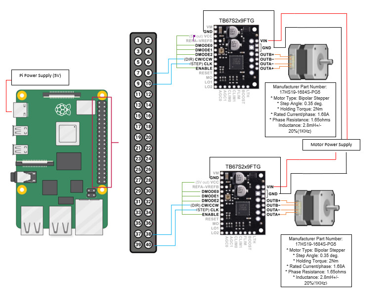
Hello. I am in dier need of with my project. I am using the TB67S249FTG Stepper Motor Driver Carrier to control a nema 17 step motor with a Raspberry Pi 4. The step motor seems like it shorts when I connect ground of the driver to GND of the Rasberry. . If i don’t connect ground of the driver the motors will turn but its vibrates and miss alot of steps. I have attachd my wiring diagram and tried so many codes but the motors still spin really choppy.
Also I am looking for a basic code to run these motors simple run program.
Ok so I used an Arduino and I was able to get the motor spinning using the code
void setup() {
 pinMode(2, OUTPUT);
 pinMode(3, OUTPUT);
 digitalWrite(2, LOW);
}

void loop(){
 digitalWrite(3,LOW);
 digitalWrite(3,HIGH);
 delayMicroseconds(20);
}
So i didnt fry my motor or my drivers like I though I may have. I think I have a programming issue with the pi and not any wiring problems. So a rasberry pi program to spin my motors would be great if anyone has one.
Hello.
I would not expect your stepper motor drivers to work without a common ground connection to your Raspberry Pi or Arduino, so please make sure all of your components share a common ground in all of your future testing.
We do not have any specific example programs to control STEP/DIR interface stepper motor drivers like these with a Raspberry Pi, but if you post your simplest complete code that demonstrates the problem here I can take a look and let you know if I see any problems.
- Patrick
Thanks Patrick when I got the motor working it was with ground brought to the arduino and raspberry. This is my code for the Rasberry Pi that I got from the internet that works ok but skips steps and isnt as fast as when I ran it with the arduino. This program is running to 1/32nd on the driver, so D0,D1, and D2 are all brought 5 vdc.
import RPi.GPIO as GPIO

DIR = 20   # Direction GPIO Pin
STEP = 21  # Step GPIO Pin
CW = 1     # Clockwise Rotation
CCW = 0    # Counterclockwise Rotation
SPR = 6400  # Steps per Revolution (360 /1.8 /32 for 1/32 step)

GPIO.setmode(GPIO.BCM)
GPIO.setup(DIR, GPIO.OUT)
GPIO.setup(STEP, GPIO.OUT)
GPIO.output(DIR, CW)

step_count = SPR
delay = .00002

for x in range(6400):
    GPIO.output(STEP, GPIO.HIGH)
    sleep(delay)
    GPIO.output(STEP, GPIO.LOW)
    sleep(delay)

sleep(.00002)
GPIO.output(DIR, CCW)
for x in range(step_count):
    GPIO.output(STEP, GPIO.HIGH)
    sleep(delay)
    GPIO.output(STEP, GPIO.LOW)
    sleep(delay)

GPIO.cleanup()
I do not see any obvious issues with your program. Can you try looking at your step signals with an oscilloscope? It would be good to compare the timing between your Raspberry Pi and Arduino. Do your stepper motor drivers work any better with the Raspberry Pi if you decrease the stepping frequency?
Also, what is the voltage between VREF (either VREFA or VREFB are okay to measure from) and GND?
- Patrick
The voltage from Vref to ground is 1.283.I dont have an oscilloscope but might be able to use one at school/work. How would I change the frequency? is that the delay time in my code?
The stepping frequency is how many pulses are sent to the driver in a second. It is set by a combination of how long your program waits after setting the step output high and how long it waits after setting the step output low (both of which are controlled by the delay value in your program):
Frequency = 1 second / (time high + time low)
The Python program you posted should apply a stepping frequency of around 25kHz, which is pretty fast, so you might try running your motor with a stepping frequency as low as a few hundred Hz to see if it works. What is the target speed for your application?
- Patrick
This is a geared stepper motor approximately 5:1. Looking for around 10 rpm.
Presuming that your stepper motor has 200 step-per-revolution (like all of our stepper motors), then even with 1/32 microstepping you should only need a step frequency of about 5.3kHz.
- Patrick