
I’m attempting to run a Nema 17 stepper motor using the Pololu A4988 stepper motor driver. I’m running the motor with a Teensy 4.0, an Arduino-based microcontroller. The main issue I’m running into is the fact that the motor outputs quite weak torque. I can stop the motor’s shaft by installing a handle and just applying some weak force with any of my fingers.
Component Data:
- FYSETC Nema 17 Stepper Motor: https://www.amazon.com/gp/product/B07GDD2X4B/ref=ppx_yo_dt_b_asin_title_o08_s01?ie=UTF8&psc=1
- Pololu A4988 Stepper Motor Driver: https://www.pololu.com/file/0J450/a4988_DMOS_microstepping_driver_with_translator.pdf
- Teensy 4.0 microcontroller: Teensy® 4.0
I’ve created a simple setup in order to run a single motor as a test run, according to the following wiring diagram:
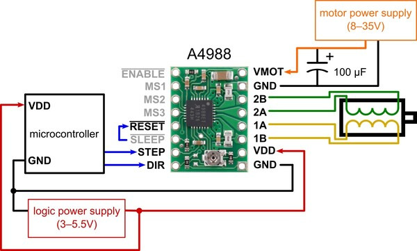
The setup:
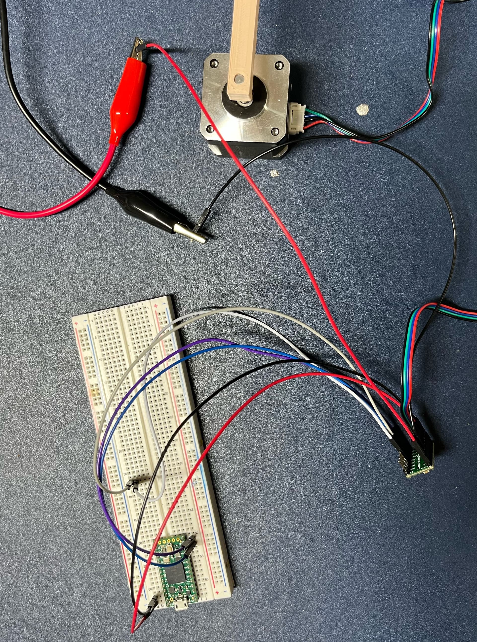

As of now, the connections are not soldered, as I’m currently just testing it. However, I’m not wiring the motor through the breadboard, instead I directly connected them to the A4988 driver with some 20 AWG wires via the connectors on the wires. For testing purposes I’m running the motor with 24V from my DC power supply, with the default current limit driver setting.
I’ve also printed out and press-fitted a handle onto the motor shaft, so that I could use to measure how strong of a torque the motors output.
The code I’m running on the Teensy:
const int dirPin = 10;
const int stepPin = 11;
const int stepNum = 400;
const int stepDelay = 6000;

void setup() {
  Serial.begin(9600);

  pinMode(dirPin, OUTPUT);
  pinMode(stepPin, OUTPUT);
}

void loop() {
  digitalWrite(dirPin, HIGH);

  Serial.println("Spinning!");

  for (int i = 0; i < stepNum; i++)
  {
    digitalWrite(stepPin, HIGH);
    delayMicroseconds(stepDelay);
    digitalWrite(stepPin, LOW);
    delayMicroseconds(stepDelay);
  }

  delay(1000);
}
Basically I’m sending pulses via the Step pin on the Teensy and delaying by 6000 microseconds after every state change on the Step pin.
The setup above allows me to spin the motor in the desired directions and desired amount of steps, however the torque the motor provides is considerably weak. I’m able to halt the printed arm and the shaft of the motor with any of my fingers without much force.
Someone on a different forum reccomended to try and set the current limit on the motor.
I followed the exact steps of this tutorial, and I set the Vref voltage by turning the current limit screw on my A4988 driver with a scredriwer, and watching the voltage across that screw and a GND on my multimeter.
As far as I understand, I need to know the sensing resistance of my A4988 driver chip in order to plug that value into the equation in order to determine my required value for Vref. The equation as far as I understand is Vref = Imot * 8 * Rsen. According to the tutorial and the Pololu datasheet on the A4988 driver, the sensing resistance can be located on a pair of resistors on the chip.
Here is an image of my specific A4988 driver:
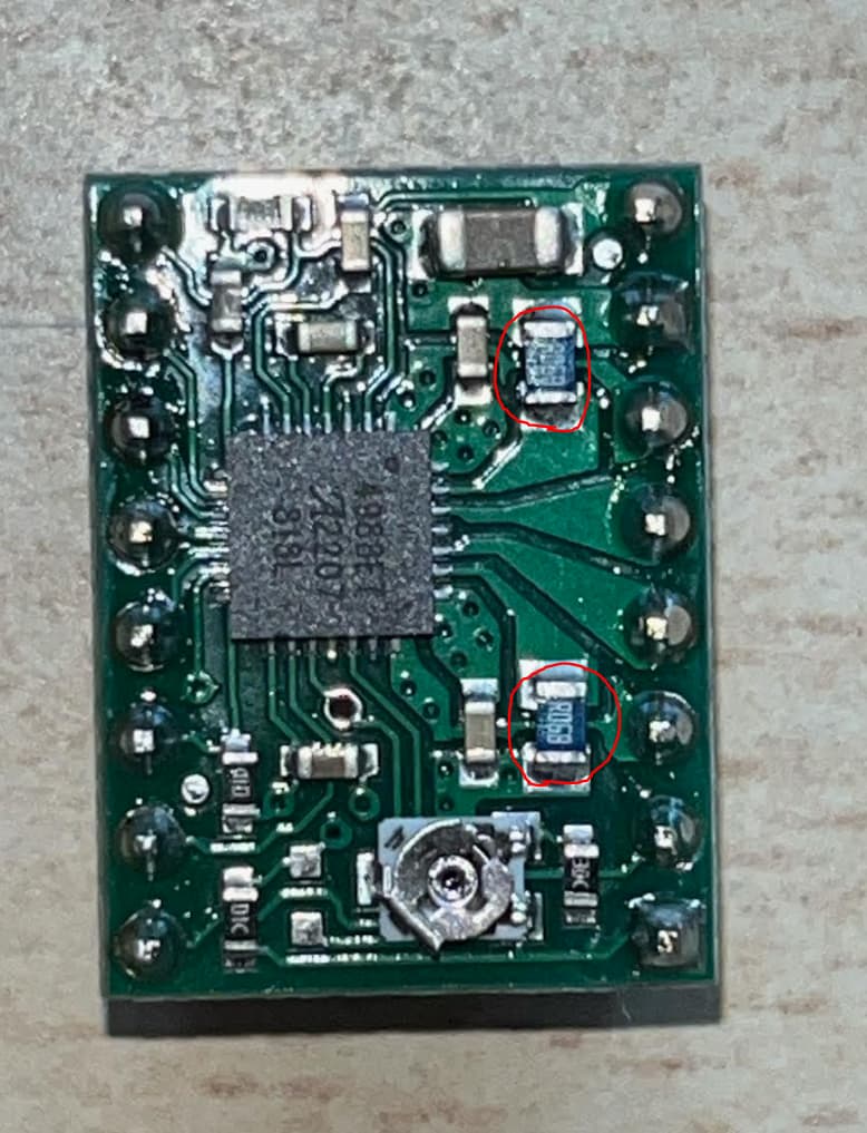
It’s a bit hard to tell, but I’m pretty sure that those small resistors say R068, which I understand stands for 0.068 Ohms of resistance.
According to the datasheet of the motor I’m using, the rated current is 1A, which is the default setup that these drivers come with. Since I’m supplying 24V with my DC power supply to the motor, I wanted to try and see whether I can supply more current to my motor, and see whether that improves the situation. I wanted to try and apply 2A of current, which means that, according to the equation above, I’d need to set the value of Vref to 1.6V. I went ahead and did that according to the tutorial, and tried to power the motor. This time the current supplied by my power supply would be significantly higher, sticking around 1.7A - 1.8A during the motor stepping.
However, as positive as this looked, the motor was still unfortunately not strong enough to surpass my fingers.
I also tried to microstep the motor by connecting the MS pins into different combinations;
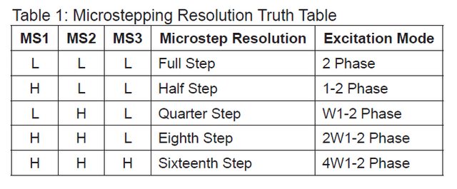
Unfortunately, that did not appear to improve the situation either, instead if made the torque even weaker.
After these trials, I consulted a friend who mentioned something I have not thought of before;
It is my understanding that a 2-phase stepper motor works by sending pulses to each one of the two bipolar coils. The current sent in these pulses energizes the coils, and creates the magnetic field that result in the movement of the motor. These pulses are created by whichever controller is controlling the driver, in my case it’s the Teensy 4.0.
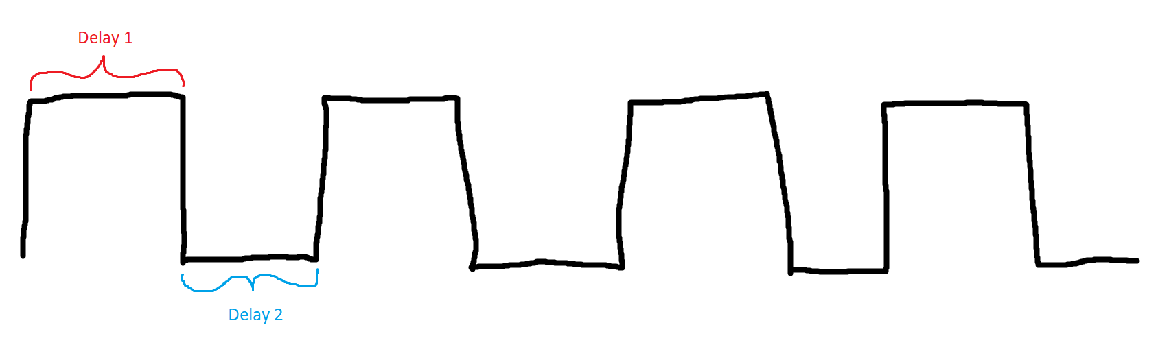
In the code I’m running on the Teensy, the actual pulses (sent via the step pin to the driver) are created by the following lines of code:
for (int i = 0; i < stepNum; i++)
{
  digitalWrite(stepPin, HIGH);
  delayMicroseconds(stepDelay);  // Delay 1
  digitalWrite(stepPin, LOW);
  delayMicroseconds(stepDelay);  // Delay 2
}
Where I alternate the step pin between HIGH and LOW, and the actual step takes place on the transition from HIGH to LOW.
Now, as far as I understand, Delay 1 in the diagram above represents the pulse width, while Delay 2 represents the pulse delay. So far I’ve only tested running these motors with both of the delays shown above being the same length. However, I was wondering whether the mystery of the low torque lies within the durations of these two delays.
What ratio between these two delay values would be appropriate for running these motors?
Another thing I’ve thought of was to try and view the actual pulses using an oscilloscope.
I conntected the oscilloscope across one of the two coils of on the driver, while it was running the motor. I wanted to track both the holding and stepping voltages on the coil. The results surprised me.
Here are two GIFs of the oscilloscope display, first as the motor is holding, second as the motor is stepping:
The thing that was very interesting to me was the fact that, while the motor is holding, there are pulses visible on the oscilloscope display. I would expect for the voltage across the coil to be stable at a certain value while the motor is holding, and not to alternate. Here is a close-up of the display while the motor is holding:

Why are there pulses that are visible while the motor is holding? Could that be a reason for why the motor is experiencing unusually weak torque?
At this point I’m kind running out of options with this Pololu A4988 driver.
I will also order a few of the TMC 2209 BigTreeTech drivers that a friend reccomended, which are also commonly used in devices like 3D printers. I will report if they improve the situation after testing them out.
Thank you for reading my post, any guidance is appreciated