Hello 
I am working on a stepper motor project using a NEMA 17. It is not strong enough to swing the rod. Here is a picture of the unit.
The rod is approximately 1.5 meters long and 20mm in diameter, and weighs almost 4.5 pounds.
I am using the Itsy Bitsy 32u4 3v microcontroller and need to swing from a home position at 20 degrees to the 180 degrees in 75ms.
I am thinking of changing the motor to a NEMA 34. It is rated at 6A/coil. With a 24V/10A power supply.
I want to use the Polola 36v8 driver, but I have some questions tho:::
-
Where can I find a doc on the HighPowerStepperDriver library that explains the functions?
Like, how do I tell the drive how much current to use?. I want to set it at 5.5A. How do I set the mode to divide the step by 16?
-
Can I hard-wire the SCS to the 3.3V rail instead of using a GPIO pin?
I have reviewed the examples, and I believe I have a good understanding of some of the library functions.
I will be using the driver’s step and dir pins to control the driver’s operation and using the serial port to set up the options.
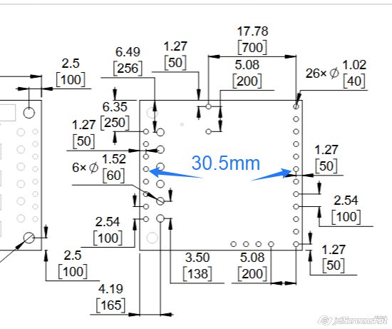
Can someone check my math? Is the distance between the pin columns is 30.5 mm (blue arrows and text).
Thank you for sharing your wisdom.
Hello.
- Here is a link to our documentation for the High-Power Stepper Motor Driver library for Arduino. (That link is also given in the library’s README.md file under the “Documentation” header.) I also recommend looking at the example programs, which show how to use some of the common functions, like
setCurrentMilliamps36v8 and setStepMode.
- The DRV8711 stepper motor driver IC used on the Pololu High-Power Stepper Motor Driver 36v8 requires logic transitions on the SCS pin for SPI communication, so SCS must be connected to a programmable output pin on your microcontroller. You can find more details about the SPI communication in the DRV8711 datasheet, which is linked to on the product page under the “Resources” tab.
- The horizontal distance between those holes is 1.20 inches (30.5 mm).
By the way, in case you have not done so already, I recommend you try to characterize the load on your motor more completely so you can more confidently assess whether switching to a larger motor will work. It is not entirely clear how the rod is installed on your motor, but if you can estimate the rod’s moment of inertia and can control your motor’s acceleration rate (which is especially critical for moving loads with high inertia), then you should be able to estimate your load’s torque and compare that to the pull-out torque curves for your motor. With a quick internet search I found this LibreTexts Physics webpage about rotational motion that looks like it might be a useful reference for that.
- Patrick
Your link about rotational motion is what I was looking for.
I guess my math is correct at 30.5mm.
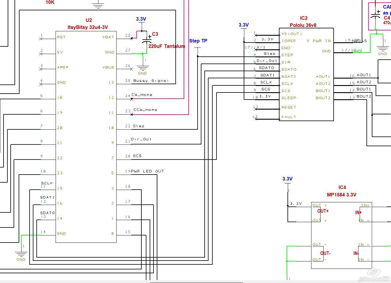
Here is a screenshot schematic (a work in progress). Do I have the hook correct?
What about the SCS signal hard wired to the 3.3V power rail?
Oops,! I see that the second answer in my previous post might have been a little unclear; I made a minor edit. SCS must be connected to a programmable output pin on your microcontroller. You will not be able to communicate with the driver if SCS is tied to 3.3V (even if it is the only device your are communicating with using SPI).
I do not see any obvious issues with your proposed schematic.
- Patrick
Thank you for sharing your wisdom.
OK, I will hook the SCS to the micro-controller GPIO pin.
Yes, the examples show the common functions. I just want to see the library’s other functions.
1 Like
One last question, if I may.
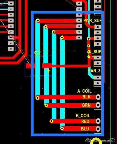
Attached is a screenshot of the PCB, highlighting the high-power traces (indicated by the blue box). The power traces are 2mm wide.
The question is, will these traces be able to handle the required 6.5 AMPs?
If not, I welcome any suggestions.
Whether your PCB traces will be able to handle a specific amount of current depends on several different factors, so I recommend using an online PCB trace width calculator to try and assess that. You can find several options for that kind of tool with a quick internet search.
- Patrick
I just want to make sure I have the PCB traces correct before I send it my PCB house to be fabricated
.
My thinking is that the drive controller SDATI (which is an input signal) should be connected to the logic controller MOSO (which is an output). So should I do the following hook-ups?
SDATO >>> MOSI
SDATI >>> MOSO
SCS >>> SCK
Am I correct?
Where do I find what data the driver sends back to the logic controller over the SDATO channel?
The connections in the original diagram you posted were correct; what you most recently posted is not. Also, there is a typo. (MOSO does not exist.)
So, the correct connections are
| Driver pin |
MCU pin |
| SDATO |
MISO |
| SDATI |
MOSI |
| SCLK |
SCK |
| SCS |
Any other I/O |
You can learn more about the feedback the driver can provide (as well as other details about the SPI inteface by reviewing the DRV8711 datasheet, which is linked to on the driver’s product page under the “Resources” tab. (Specifically, it sounds like you might be interested in the STATUS register descriptions in section 7.6.9).
- Patrick
Thank you for sharing your wisdom
I do not know why I am so confused with these hook-ups. Maybe since this is my first app using the SPI interface.
I just want feedback to let me know that the driver is booted up and working properly, and as expected.
There is not a specific process for checking driver operation like that, but you might consider doing something like writing to one of the registers then reading the register back to make sure it was set as a basic check that the driver is working. If you are using our Arduino library, an easy way to do that would be to set the current limit using the setCurrentMilliamps36v8() function (or one of the many other functions that involves writing to the SPI registers), then use the verifySettings() function to check that your settings were applied.
- Patrick
Thank you big time. Your link is the info I was looking for. Without those links, I would never have known about the verifySettings function. In the examples, this function is never called.
Yes, I’m using the Arduino library,
Perhaps I should mention that I am not a novice ( nor an expert) in coding. I have experience with Python, Arduino, PICAXE, AutoCAD scripting, to name a few.
I have a GitHub account, but do not know how to navigate it.
Again, a BIG thanks for sharing your wisdom. 
I’m glad to hear it was helpful for you! Good luck with your project!
- Patrick