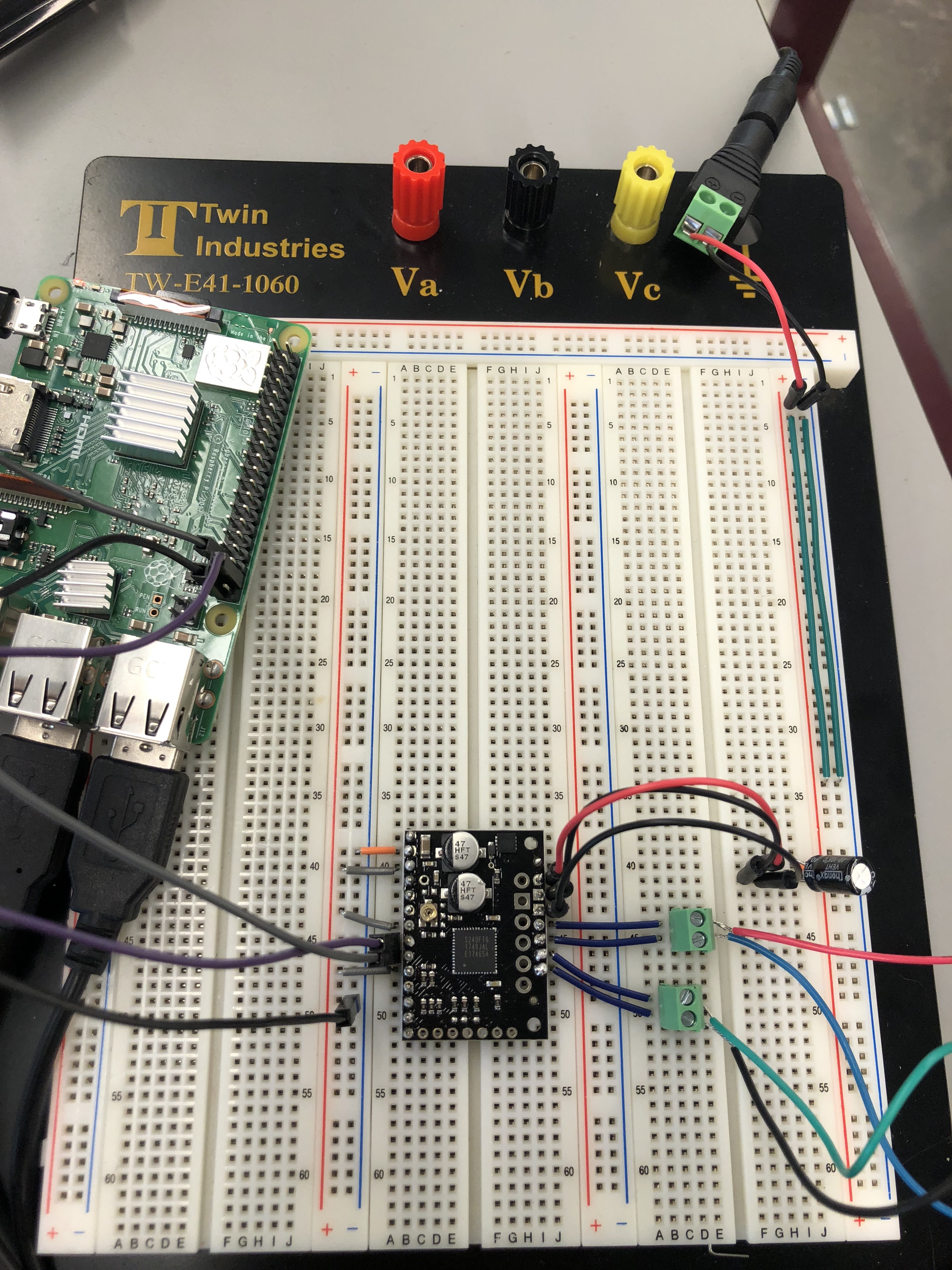
I recently purchased a TB67S249FTG stepper motor driver to use but am having some issues using it. I have read through the manual for the driver and have wired everything as it seems like I’m supposed to but the motor will not turn. Here is a picture of my current wiring – I have verified all power supplies are working (12V supply and the 5V VCC, as well as the proper VREF to supply 1.7A to the motor).
Any support or feedback on improving the wiring would be appreciated. The goal for now is simply to use the full step functionality – more complicated applications will come after I am more comfortable using the driver basics.
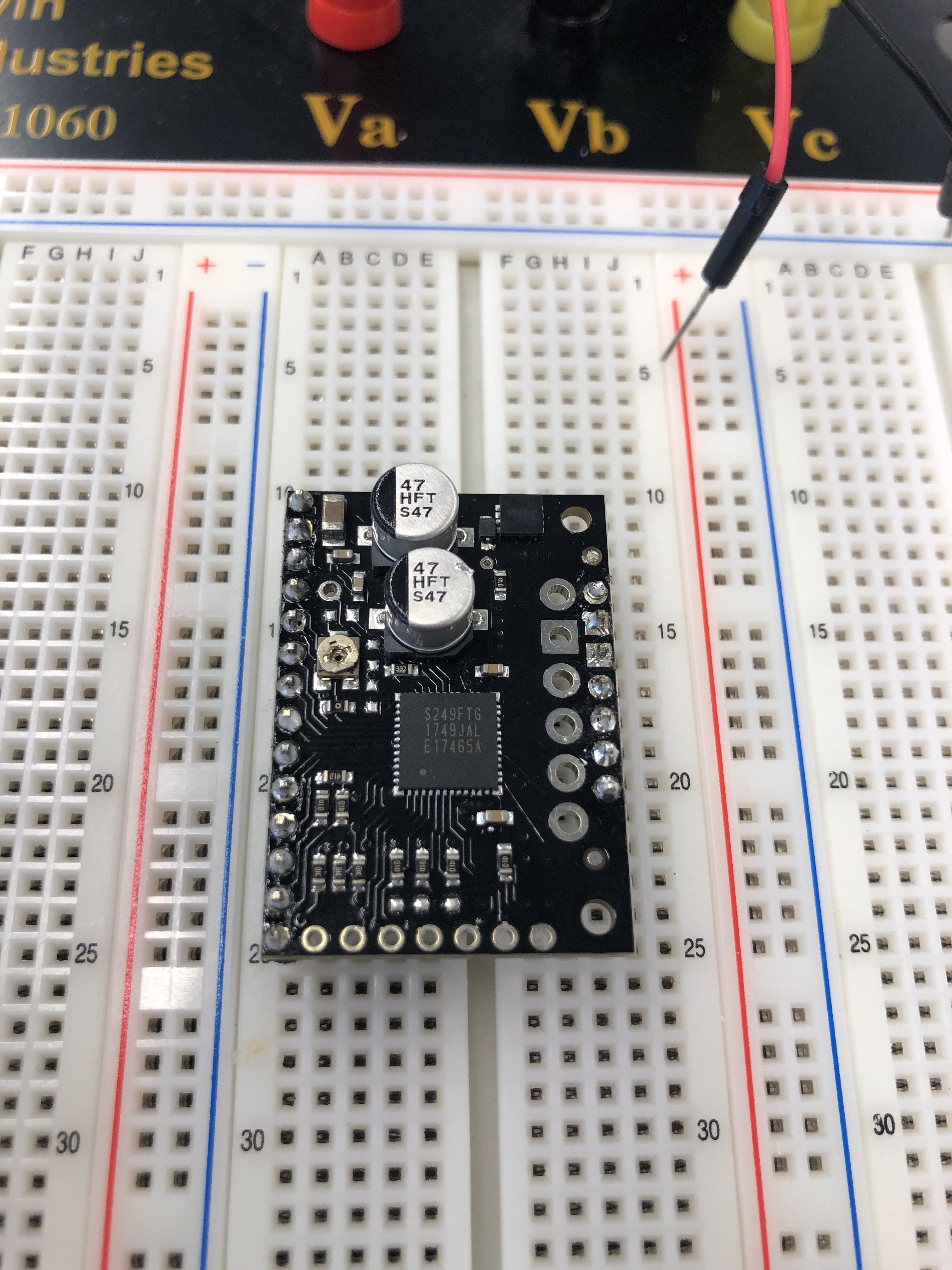
It looks like your soldering could use some touch-ups, especially on the motor output pins and power supply pins. The soldering should look like the ones in the tutorials linked on this page. Also, you should put your electrolytic capacitor as close as possible to the VIN and GND pins on the driver. If you are still unable to get your stepper motor to step, please post a close-up pictures showing the touched up pins on the TB67S249FTG carrier and the code you are running on your Raspberry Pi.
The VIN pin still does not look like it is making good contact with the pad on the board. The solder should look like mini volcanoes as shown on this common soldering problems page. Some of your solder joints look like the examples of insufficient wetting in that guide. Could you try touching it up again and then do a continuity test between the pad on the board and the header pin to make sure all the connections are good? You might need to use more solder or a hotter soldering iron.