
Hello everyone,
I need some help with my Wild Thumper. My goal is to make 4 motors to run, 2 in the front and 2 at the back, but for now i’ve been able to make only 1 work. I’m using the VNH5019 controller because the others were’nt in stock anymore.
Seems like the M2PWM (10) pin doesn’t work, everytime I connect a motor to it it won’t work, But the M1PWM pin works well. Also, there’s only 2 motors output, and i have 4 motors, how am I suppose to make it work? The VNH5019 was listed by Pololu as one of the controllers to use with the Wild Thumper so my guess is that there’s a solution to my problem.
I’ll answer any questions, keep in mind I’m not that good of a programmer though.
Thank you
Hello.
Could you tell me more about your setup? Are you using the VNH5019 as a shield? Could you post pictures of your setup showing all your connections? What are you using to supply power to the shield?
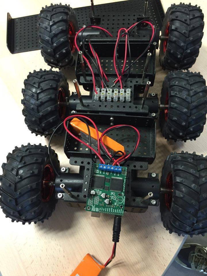
To command all four motors, you can connect two motors in parallel to each motor channel with each side of the chassis making up one channel (the two left motor make one channel and the two right motors make the other channel).
Grant
Hello,
thanks for the advice on how to connect 2 motors on 1 output.
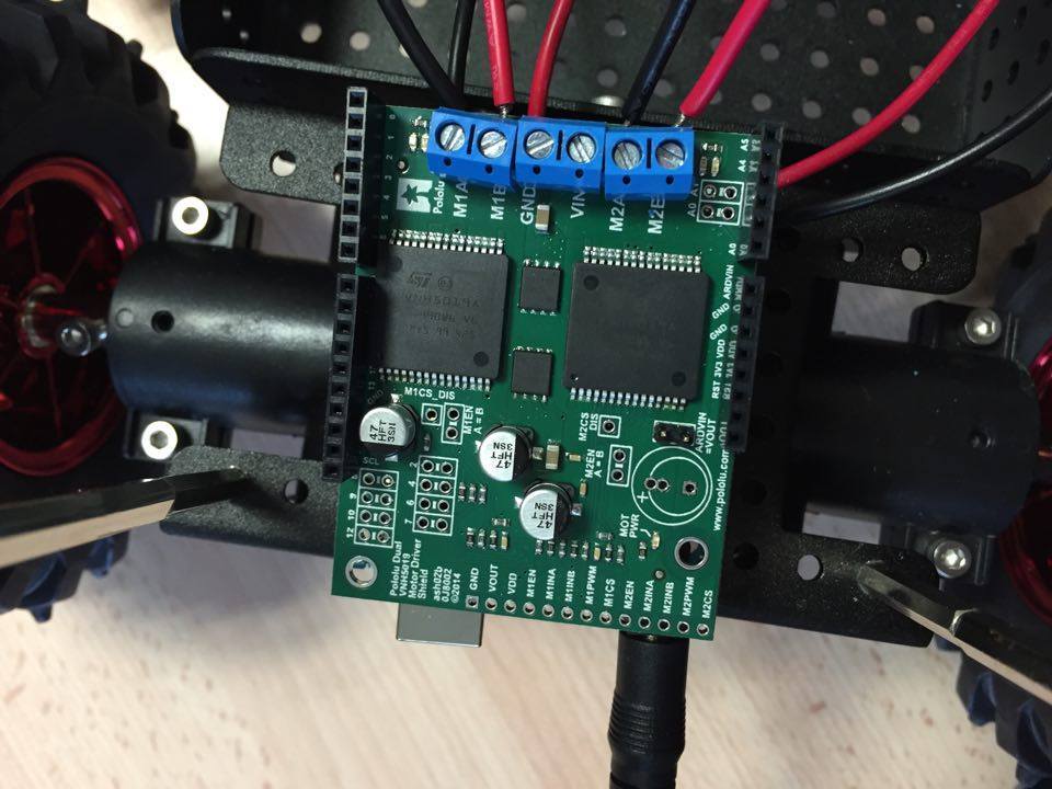
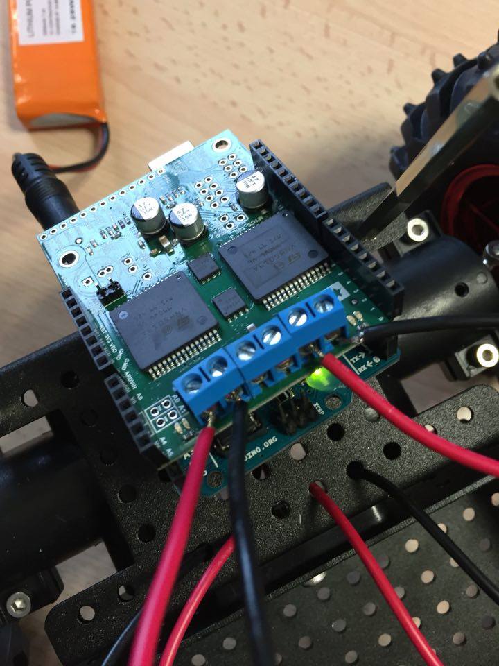
We’re using the VNH5019 as a motor shield for the Arduino Uno. To supply power we use two 7.4V 2200mAh batteries.
Anyway here are pictures on how we connected 2 motors and the batteries. The LED on the right side of the M1 lights green as it should but the one of the M2 doesn’t light at all and the M2 doesn’t make the motors run. So my guess is that the weld wasn’t done right or there’s a problem with the M2 connectors.
Well actually the M2 LED lights red now
Hello.
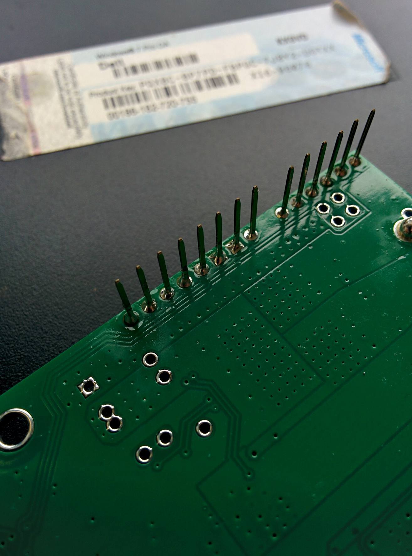
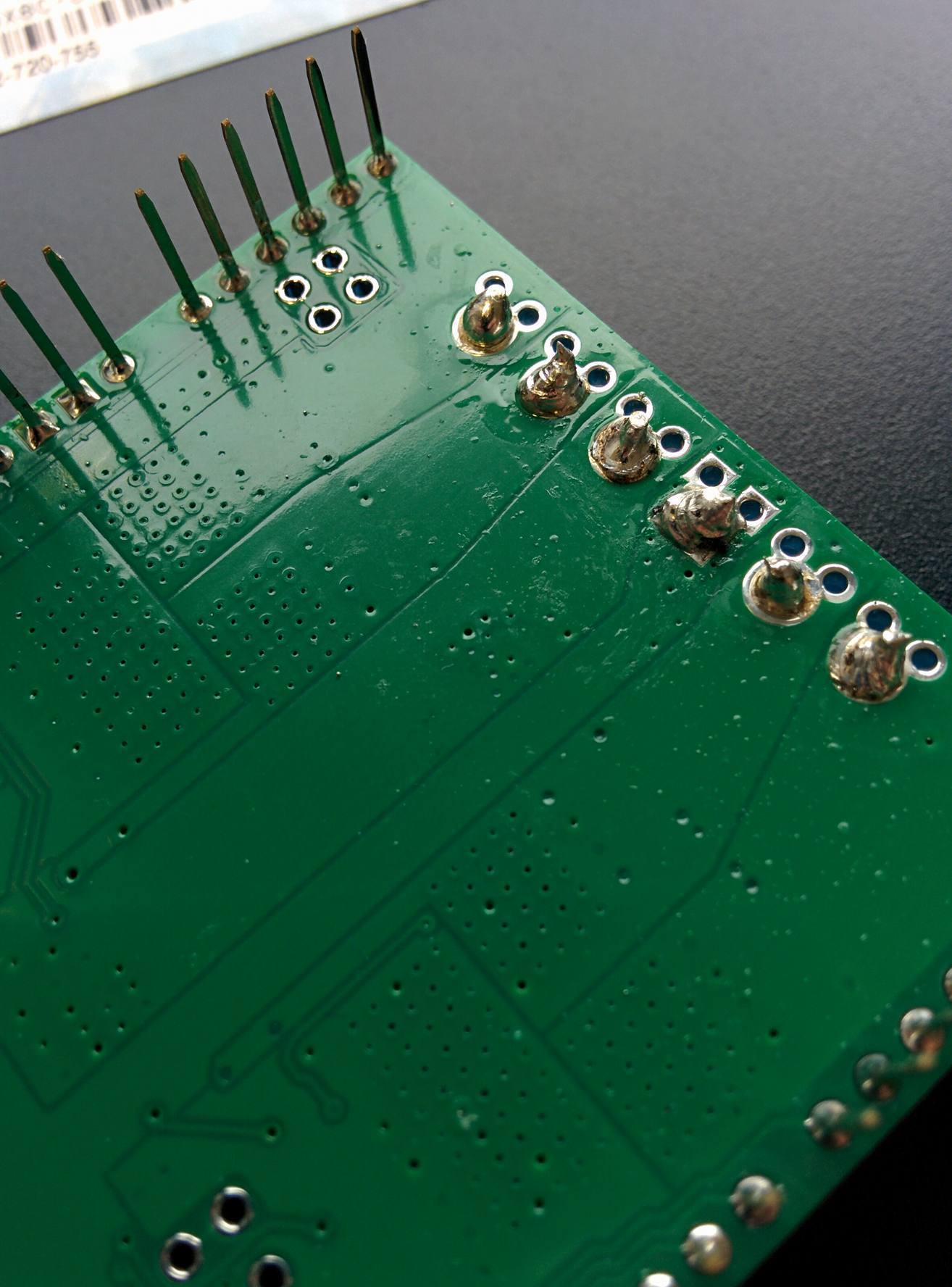
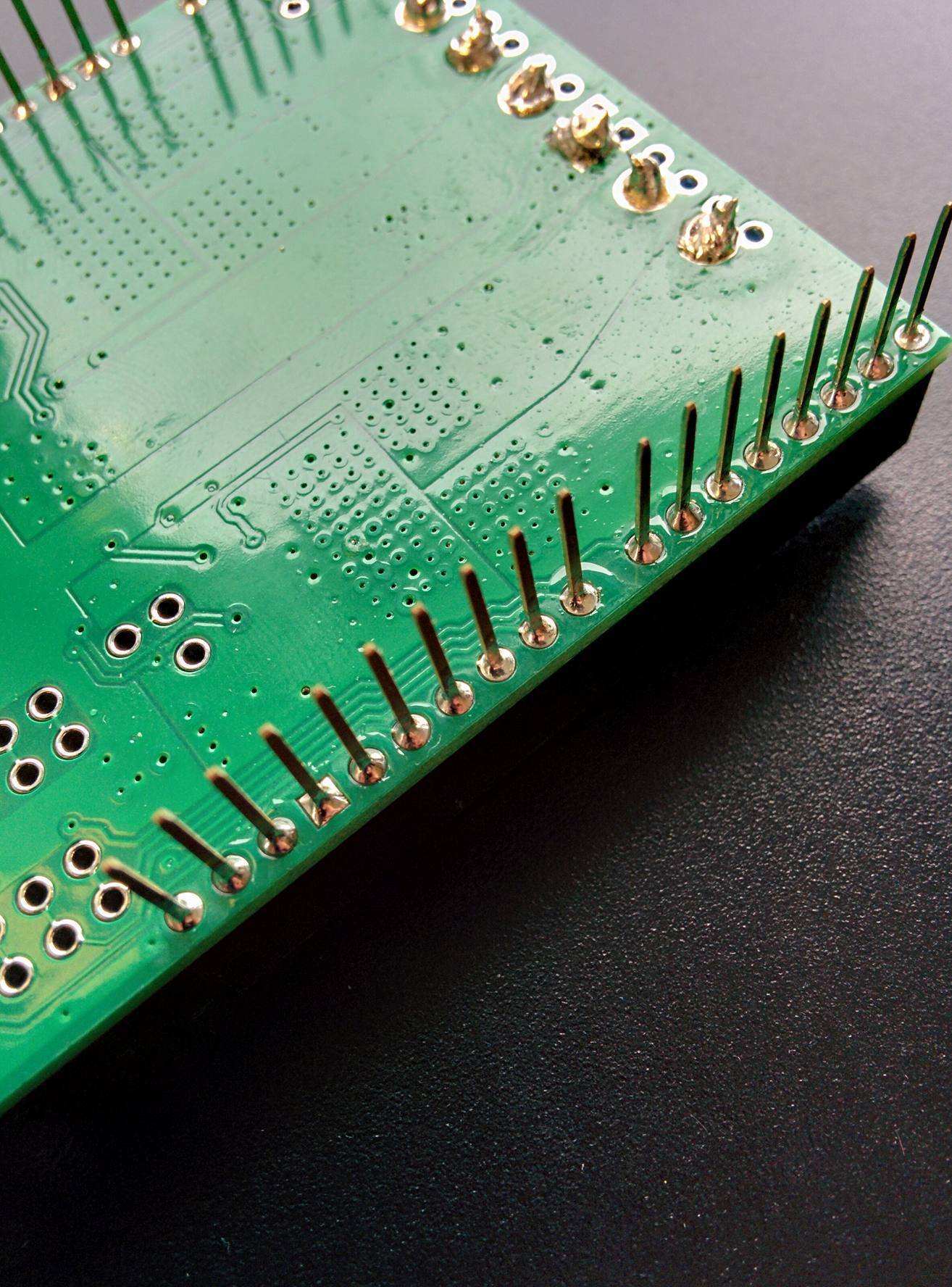
It might be a connection problem. You should check the soldering to see if that is causing the problem. If you post pictures of the soldering, I could also take a look and give you feedback.
Grant
Hello, here are pictures. Sorry for the long reply but I wasn’t able to access the robot for a while.
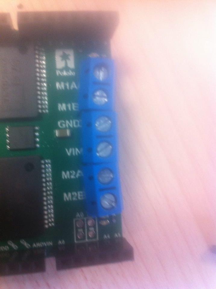
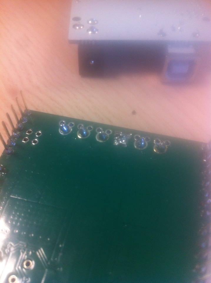
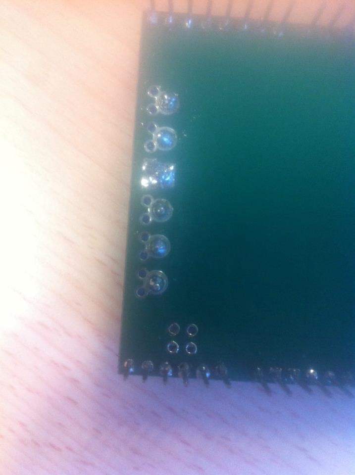
From you pictures, it looks like your solder joints are not making good connections. Try retouching the solder joints and see if that fixes the issues. If you are having trouble soldering, you might find this soldering guide helpful.
Grant
Hello,
We desoldered everything then soldered everything back up properly. Still having issues, the M1 LED lights green and the M2 LED lights red. So my guess is we broke something with the connectors inside M2 or our program has issues. Could you check it? Thanks
int pwm_1 = 9;  //PWM control for motor outputs 1 and 2 is on digital pin 3 (or 5,6)
int pwm_2 = 10;  //PWM control for motor outputs 3 and 4 is on digital pin 9 (or 10,11)
int dir_1 = 2;  //direction control for motor outputs 1 and 2 is on digital pin 2 (or 4,7)
int dir_2 = 8;  //direction control for motor outputs 3 and 4 is on digital pin 8 (or 12,13)

void setup()
{
  pinMode(pwm_1, OUTPUT);  //Set control pins to be outputs
  pinMode(pwm_2, OUTPUT);
  pinMode(dir_1, OUTPUT);
  pinMode(dir_2, OUTPUT);

  analogWrite(pwm_1, 255);  //set both motors to run at (100/255 = 39)% duty cycle (slow)
  analogWrite(pwm_2, 255);

}

void loop()
{
  digitalWrite(dir_1, HIGH);  //Set motor direction, 1 low, 2 high
  digitalWrite(dir_2, HIGH);  //Set motor direction, 3 high, 4 low

  delay(1000);

  analogWrite(pwm_1, 100);  //set both motors to run at 100% duty cycle (fast)
  analogWrite(pwm_2, 100);

}
In your first post, you said the issue was that motor channel 2 was not working at all. Since resoldering, it sounds like the issue has changed and now both motors work but only in one direction. Is that correct? The code you posted only moves each motor in one direction. Could you try our example for the VNH5019 shield instead. You can find our VNH5019 shield library, which contains the example, on our git hub page. Could you also post pictures that show your soldering after cleaning it up so I can double check it?
Grant
Hello,
No that’s not it. Since resoldering nothing works. M1 lights green and M2 lights red but the motors won’t run for some reason. This is the program I used before when the motors were running and I did not change anything so I think it’s a hardware problem.
I’ll try the library and keep you updated.
Let me know if the library works you. If it does not fix the issue, could you post some pictures showing the new soldering?
Grant
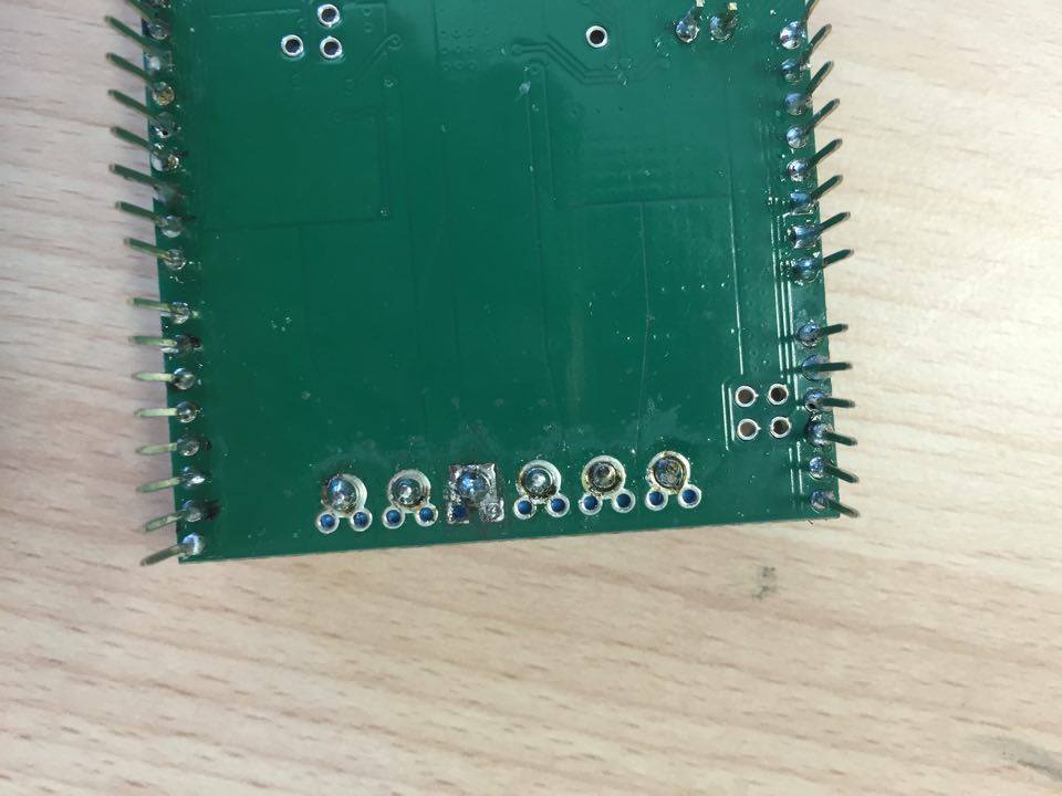

The soldering looks like it isn’t making a good connection. This time when you try to fix it, you do not need to desolder the pins. Just reheat and get the solder to re-flow (you might need to add solder though). In addition to the website with the tutorials I pointed out earlier, you might find this Adafruit video on soldering helpful:
Grant
Ok thanks a lot. We got a new motor shield and it’s working perfectly. The only problem is that we still can’t make M2 run. Both LED light green but M2 motors won’t run. Here’s the program:
#include "DualVNH5019MotorShield.h"

DualVNH5019MotorShield md;

void stopIfFault()
{
  if (md.getM1Fault())
  {
    Serial.println("M1 fault");
    while(1);
  }
  if (md.getM2Fault())
  {
    Serial.println("M2 fault");
    while(1);
  }
}

void setup()
{
  Serial.begin(115200);
  Serial.println("Dual VNH5019 Motor Shield");
  md.init();
}

void loop()
{
  for (int i = 0; i <= 200; i++)
  {
    md.setM1Speed(i);
    stopIfFault();
    if (i%100 == 100)
    {
      Serial.print("M1 current: ");
      Serial.println(md.getM1CurrentMilliamps());
    }
  }


  for (int i = 0; i <= 200; i++)
  {
    md.setM2Speed(i);
    stopIfFault();
    if (i%100 == 100)
    {
      Serial.print("M2 current: ");
      Serial.println(md.getM2CurrentMilliamps());
    }
  }


}
Hello.
Since you have a new board, could you post a picture showing the soldering?
Grant
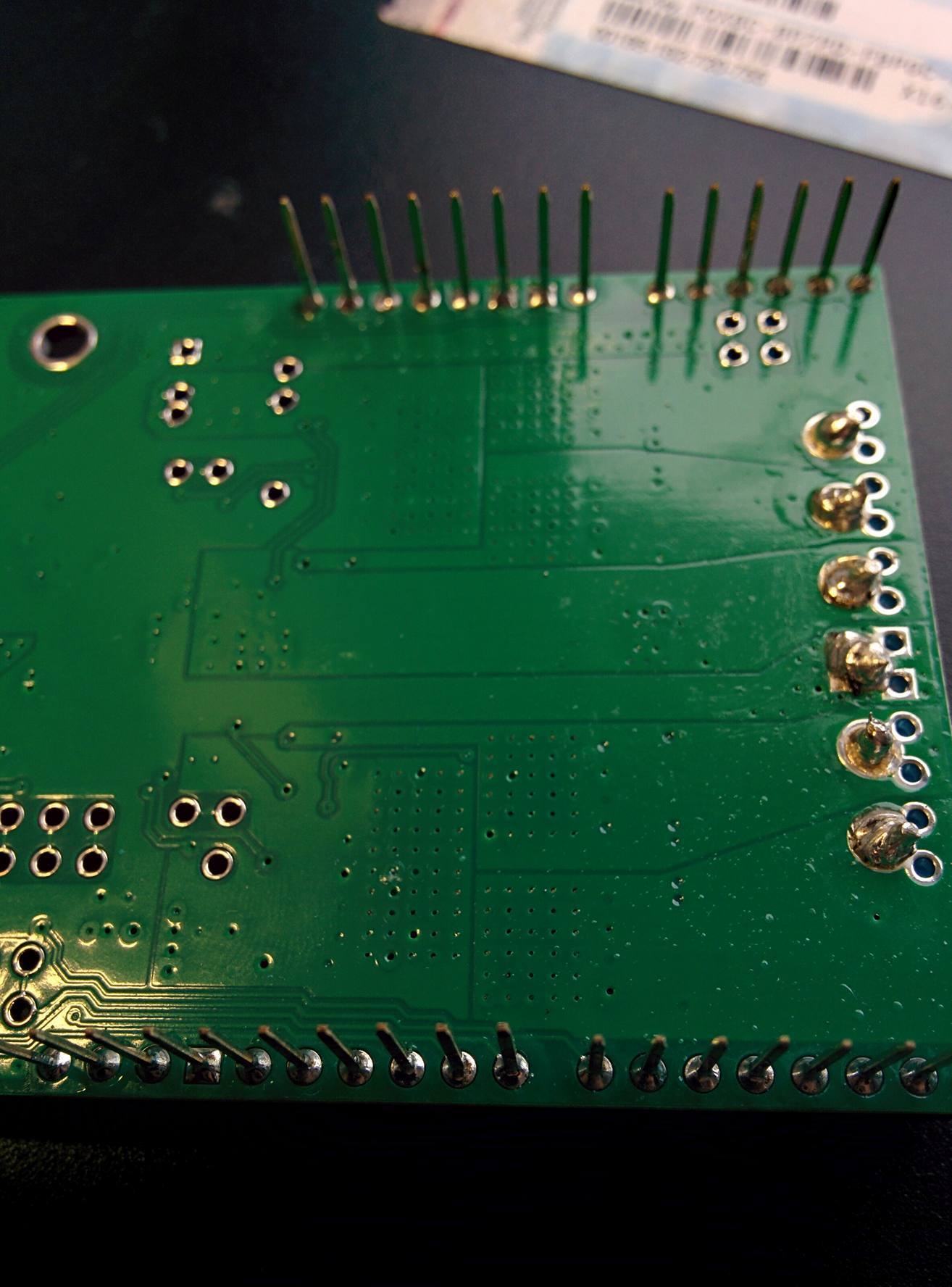
Since you are getting the LEDs to light, I do not suspect a program problem. From the pictures, it looks like you should touch up the soldering on the terminal blocks. Also, just in case, could you also use the example program without making any changes to it?
Grant
It’s really hard to make a perfect soldering since the terminal blocks’s holes are big and need to be filled.
I’ve tried to use an example of the program without making any changes and both LEDs flash green then red. With a 2 secons interval.
Hello.
From the boards response, it sounds like the board is working correctly. Do you have motors connected? If the motors are not responding, could you try directly powering the motors to make sure they work?
By the way, since the pads for the terminal block are larger, you might need to hold the soldering iron to them for longer to get the solder to flow.
Grant