
Hi everyone, I’m having a problem with the MP6500 Stepper Motor Driver i recently purchased from Pololu. Here is a link to the product (Pololu - MP6500 Stepper Motor Driver Carrier, Digital Current Control), I have the model with digital current control. In short, when I apply a signal with a pulse-width with a 5V amplitude to the STEP input on the chip and measure the voltage at STEP, only a pulse-width of 2V is measured.
To go into more detail, here is a picture of the circuit on my breadboard

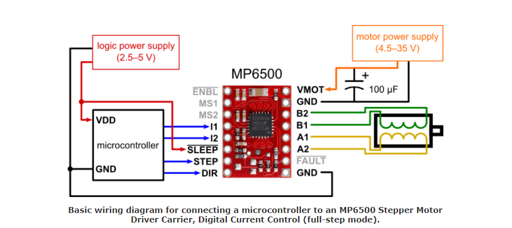
So, I wrote code to output a high signal to STEP for 1 second and then output low for 1 second, switching over and over again. Here’s the code (motor_test_ex (145 Bytes) ). The driver’s data sheet (https://www.pololu.com/file/0J1447/MP6500_r1.0.pdf), also found on the product page, says that the motor will advance one step on each rising edge of the pulse. So, I connected nSLEEP, waited a second for the chip to stabilize, then ran the code and connected the pulse width output from my arduino to STEP. I measured the voltage at STEP and it was alternating between 2 V when high and 0 V when low, instead of 5V and 0V. I also measured my voltage divider output and it alternated between 2.5 V and 2.4V whenever my pulse to STEP transitioned from high to low. I also measured the 5V power rail and nSLEEP input and they alternated between 5V and 4.9V whenever my pulse to STEP transitioned. I removed my pulse to STEP and placed it on a separate area of the breadboard and measured it and found that it was working correctly, going from 5V high to 0V low. I measured my power and voltage divider and they were back to normal. However, as soon as I plugged in my pulse to STEP, the same problems occurred. Unsure of the problem, I tried switching the output pins on my arduino where the pulse was coming from, but that didn’t solve anything.
Later, I tried giving STEP the same 5V DC from the arduino that nSLEEP was getting. I measured STEP at 4.9V instead of 5V. My 5V power rail and nSLEEP also got dragged down to 4.9V instead of staying at 5V. My voltage divider became 2.4V instead of 2.5V. Removing the connection from STEP fixed the problems with the power rail and voltage divider.
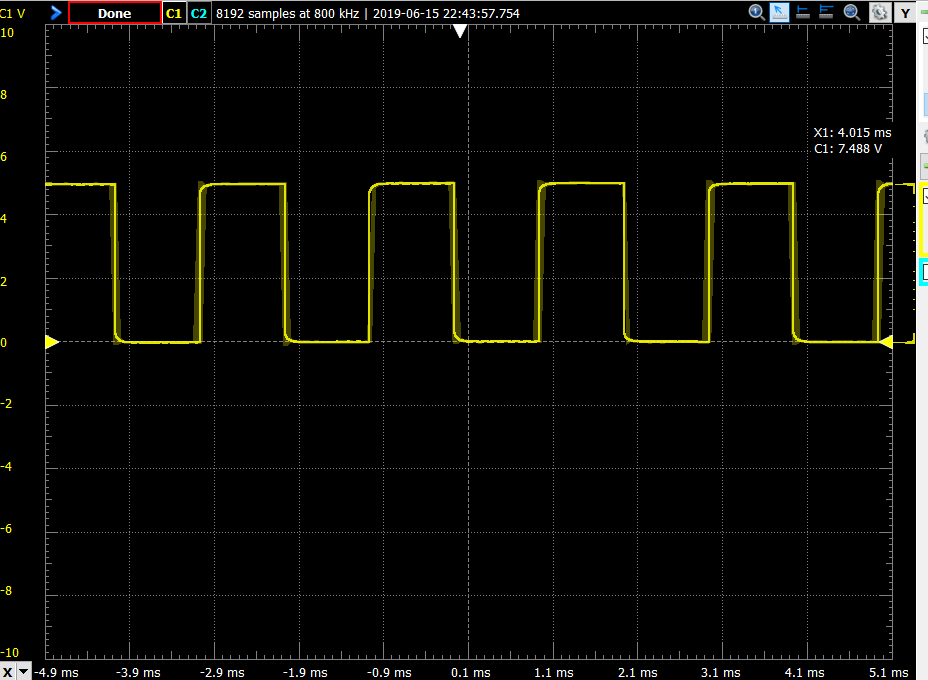
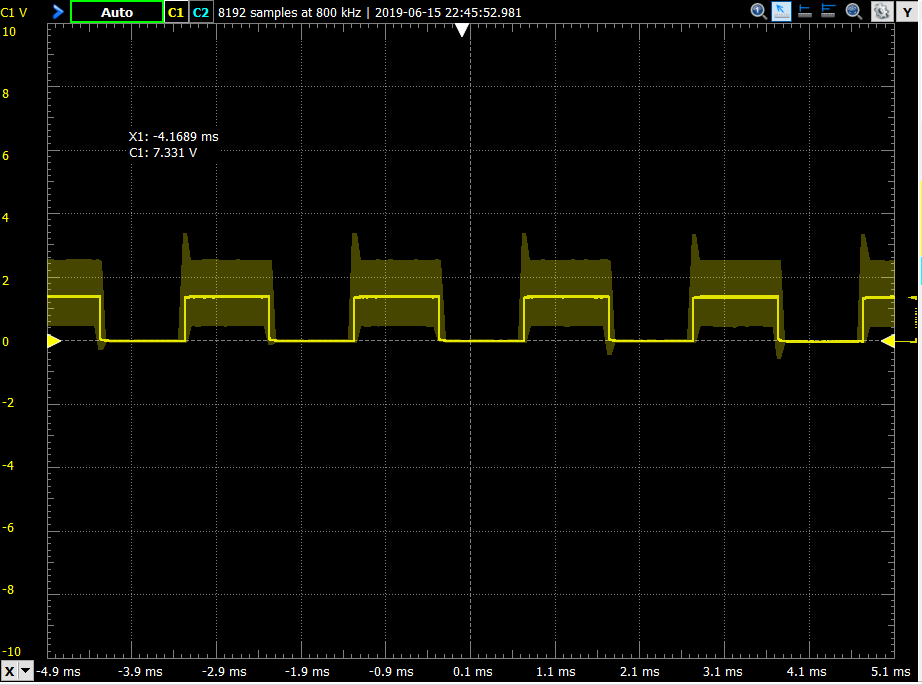
I eventually tried using my Analog Discovery (USB Oscilloscope and Logic Analyzer - Digilent Analog Discovery 2) to output a square wave of 5V at a higher frequency (it was 1kHz or lower) to STEP. Here is the oscilloscope output of the wave before I connected it to STEP ( . As you can see it’s exactly what it should be. After connecting it to STEP, here was the oscilliscope output ( ). The signal became very messy and had an amplitude of less than 2V.
I have no idea what the problem is. I’ve carefully read the datasheet and product page, rechecked my wiring and looked online is having similar problems.
Also, for context, here is my stepper motor (Pololu - Stepper Motor: Bipolar, 200 Steps/Rev, 28×45mm, 4.5V, 0.67 A/Phase). Before we realized that STEP’s input wasn’t working correctly, we wired the chip fully and connected the motor. The right side power rails of my breadboard had a 5V 4A power supply for the motor connected connected to them. The motor slightly turned and then stopped moving. I didn’t include this above because the primary problem is with STEP somehow getting the wrong voltage and the chip should still work fine without the motor connected. I’m assuming that the STEP issue was the cause of the motor not working correctly. I’m using this chip for an engineering project with an approaching deadline and would appreciate any advice or direction anyone could give me. Thanks!