
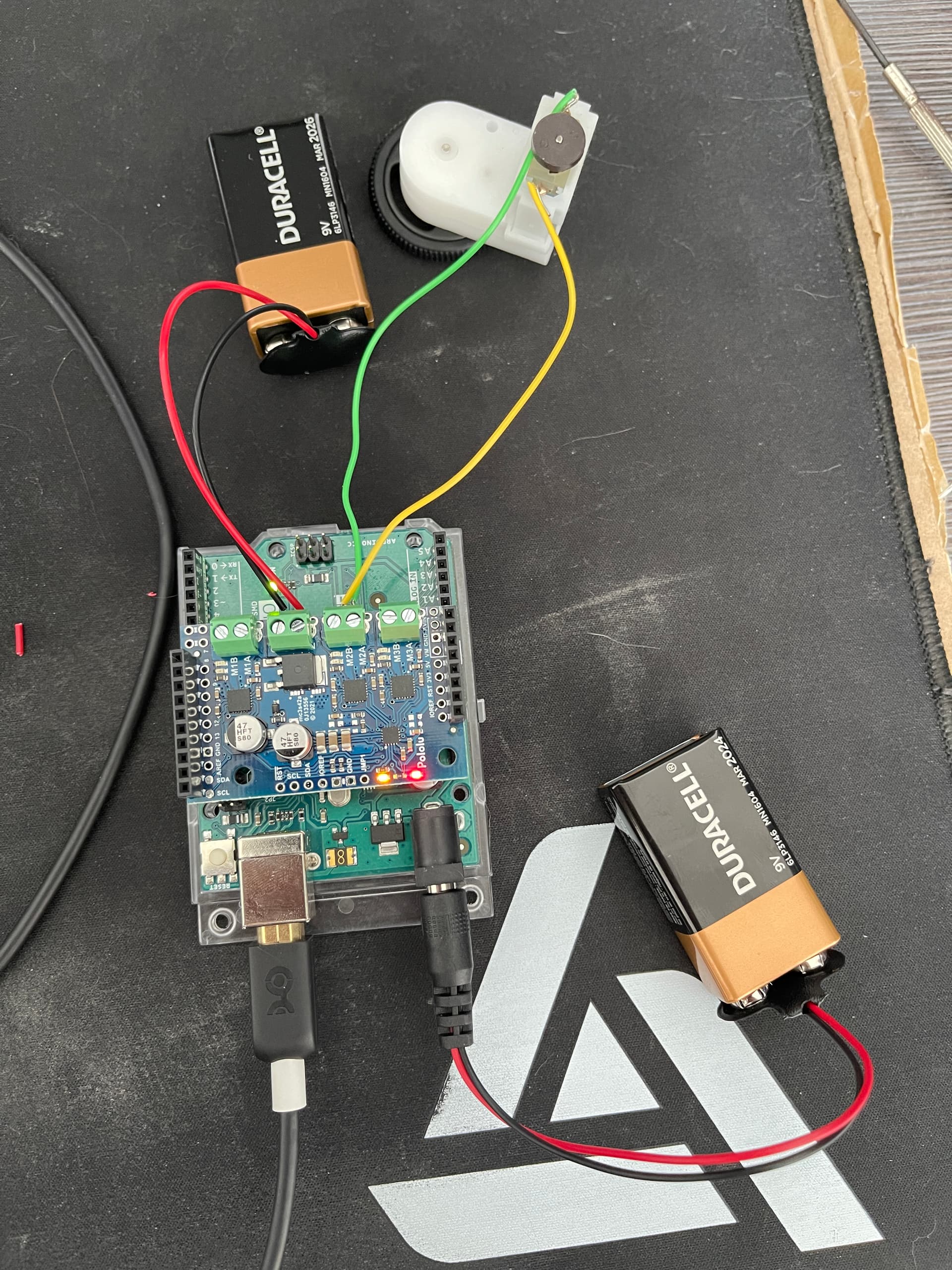
I have tried all MOut ports with a DC motor and had no results. The only thing I have had happen is the Green or Red LED will light near the M1A or M2A etc port if I plug one of the two wires directly into the 5V socket on the motor shield. I’m very new to this all so forgive me if it is a simple error. My Arduino Uno is running on USB power, as well as a 9V battery. The pololu plugin between M1A and M2B is also wired directly to a 9V battery. I have swapped Pos and GRND input wires to this slot with no change in results.
Hello.
Alkaline 9V batteries are not appropriate for powering motors since they cannot supply enough current. Do you have another type of battery or battery pack that you could use to power the Motoron M3S256 shield and your motors?
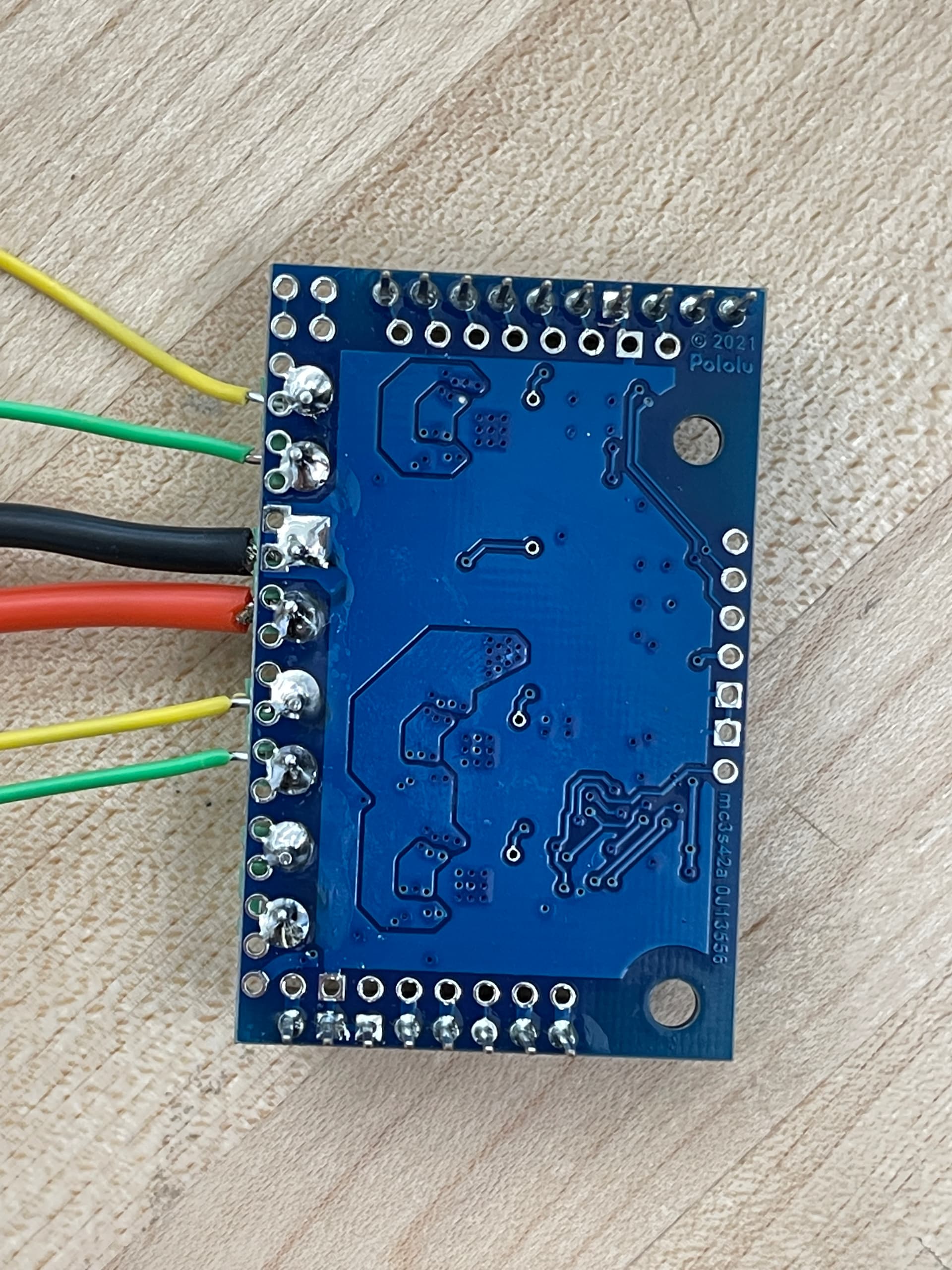
If switching to another power supply does not work, can you remove the Motoron from your Arduino and post some pictures of the bottom side of the board so I can check the soldering? Also, please try running our unmodified Simple.ino example program from our Motoron Arduino library with the motors disconnected and let me know what the LEDs on the board do.
Also, it is not entirely clear what connection you were adding that caused LEDs to turn on, but please refrain from making any additional connections until we have confirmed that your motor controller is working.
- Patrick
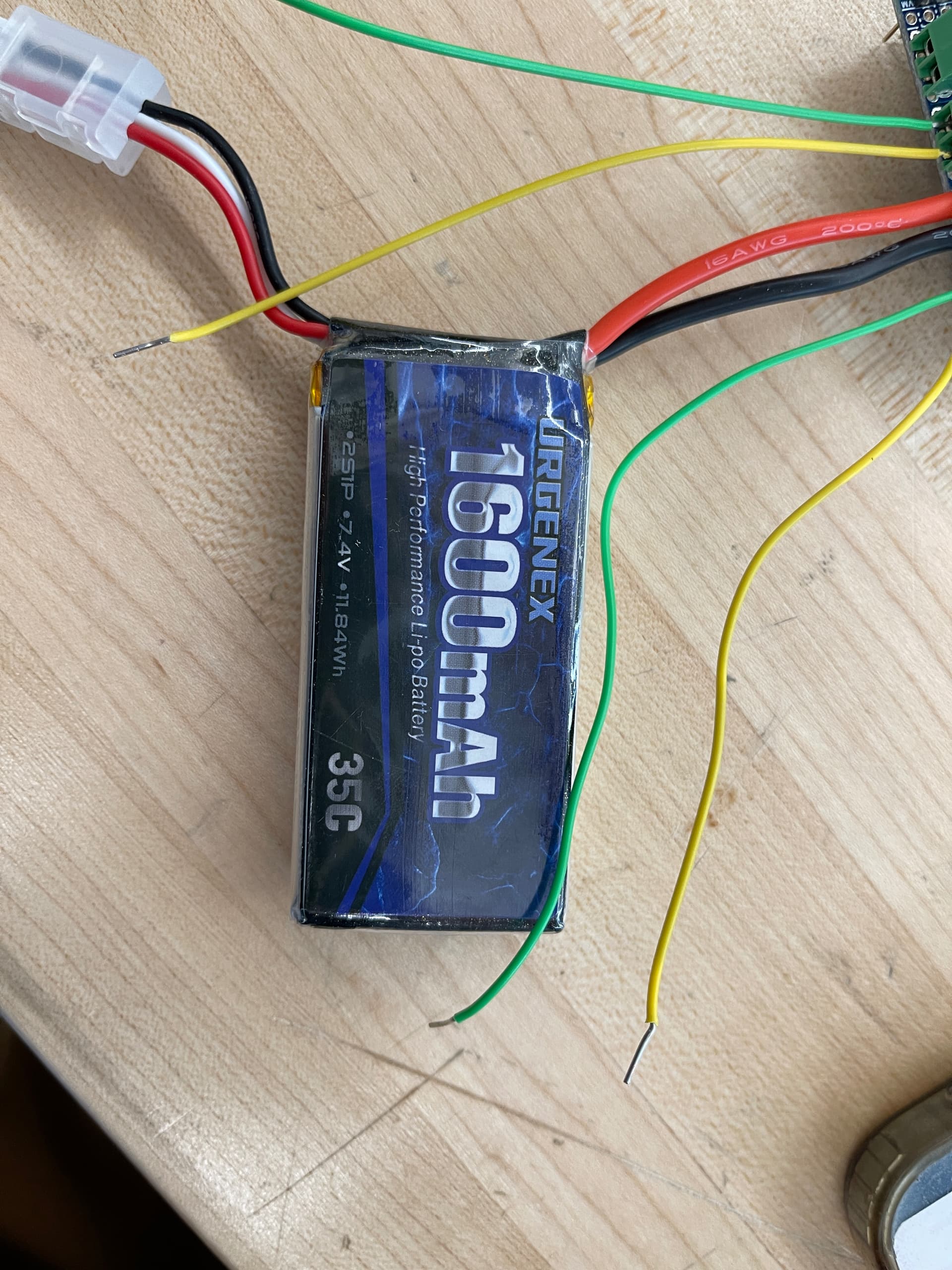
I purchased a 7.4V 2C NiMh battery that I hope works, I will update you when I get a chance to testing.
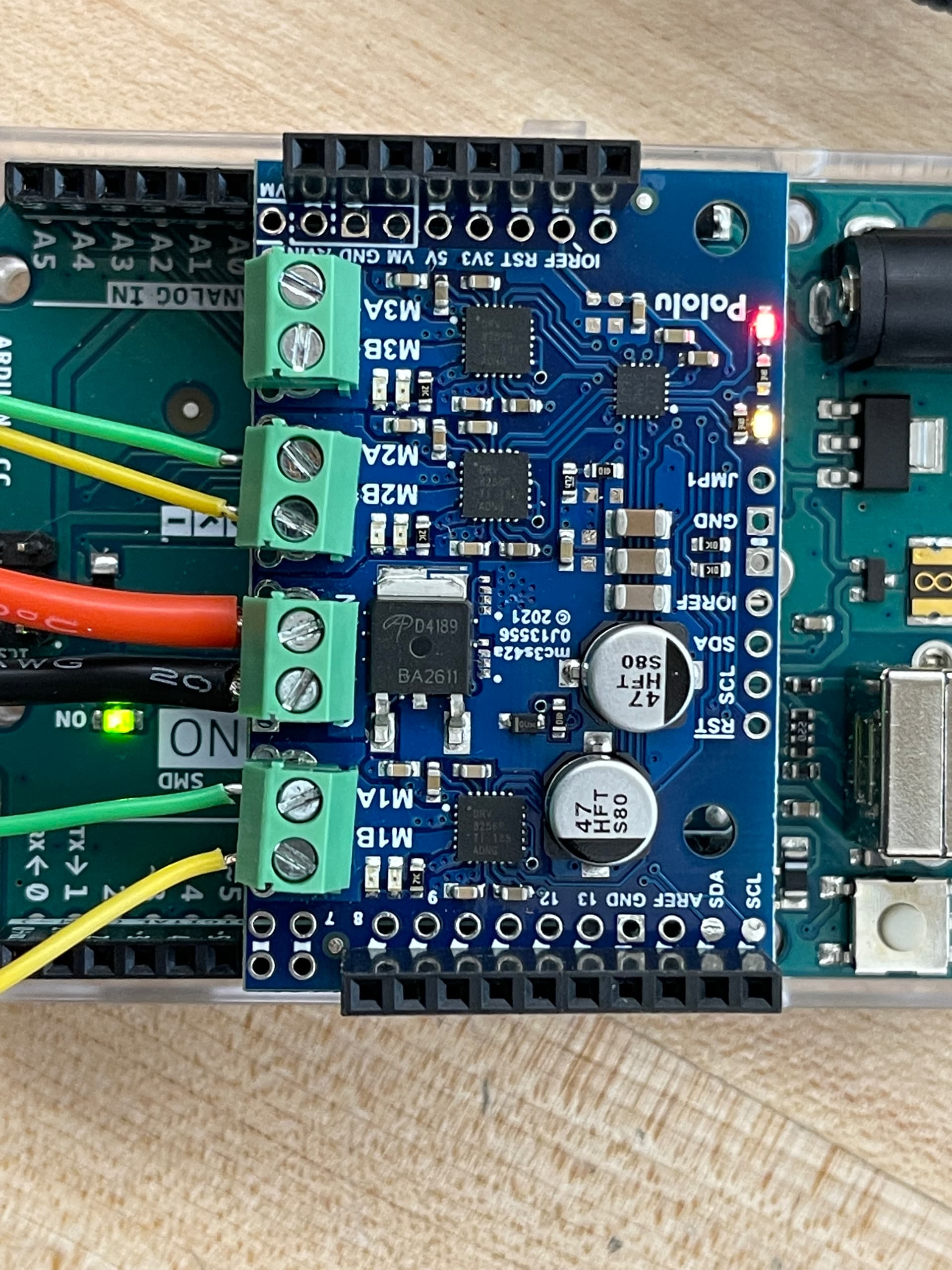
After further review, it seems we possible have the wrong Arduino. In a lot of the photos on pololu’s website, the Arduino UNO used for this motor shield has a larger, black, rectangular chip in the middle. Ours does not. If this is not the issue however, I’ve attached some images. The simple.ino code still does not work. The image of the motor shield with all the lights on shows wires going out for the motors but none are connected and the wires are not touching out of frame either so there should be no loop.

Also attached here is the Arduino REV 3 that I believe we may be in need of with the large rectangular chip.

It looks like you have a Arduino Uno SMD, which should be fine for controlling your Motoron.
Could you tell me exactly what the LEDs are doing on your board when simple.ino is running, or could you post a video showing their behavior? The forum does not allow users to post very large videos, but it does work well with videos linked from YouTube, so you could upload a video on YouTube (unlisted if you prefer) and link to it here. Also, please use a multimeter to check what voltage is being applied to the Motoron’s main VIN and GND pins as well as on the motor output pins when the program is running.
Can you also try running the unmodified careful.ino example program with your Arduino connected to your computer via USB and let me know what gets reported in the Arduino Serial Monitor?
- Patrick

And careful.ino reported “Communication Error: 2”
We measured the voltage at 7.4 from the battery. No voltage while running the program from the individual terminals.
Also no motors are connected, just wires which are not connected out of frame.
The error message suggests that the Arduino is not getting a response from your Motoron controller. That suggests either a broken pin or connection, or the wrong address is being used to communicate with the Motoron.
Can you try uploading the SetI2CAddresses.ino example sketch to your Arduino, opening the Serial Monitor, and then using that to send an “s” using the Serial Monitor? The “s” command does a simple scan of the bus to see which addresses have devices responding.
Also, do you have another Arduino Uno, another Motoron, or any other I2C devices available?
- Patrick
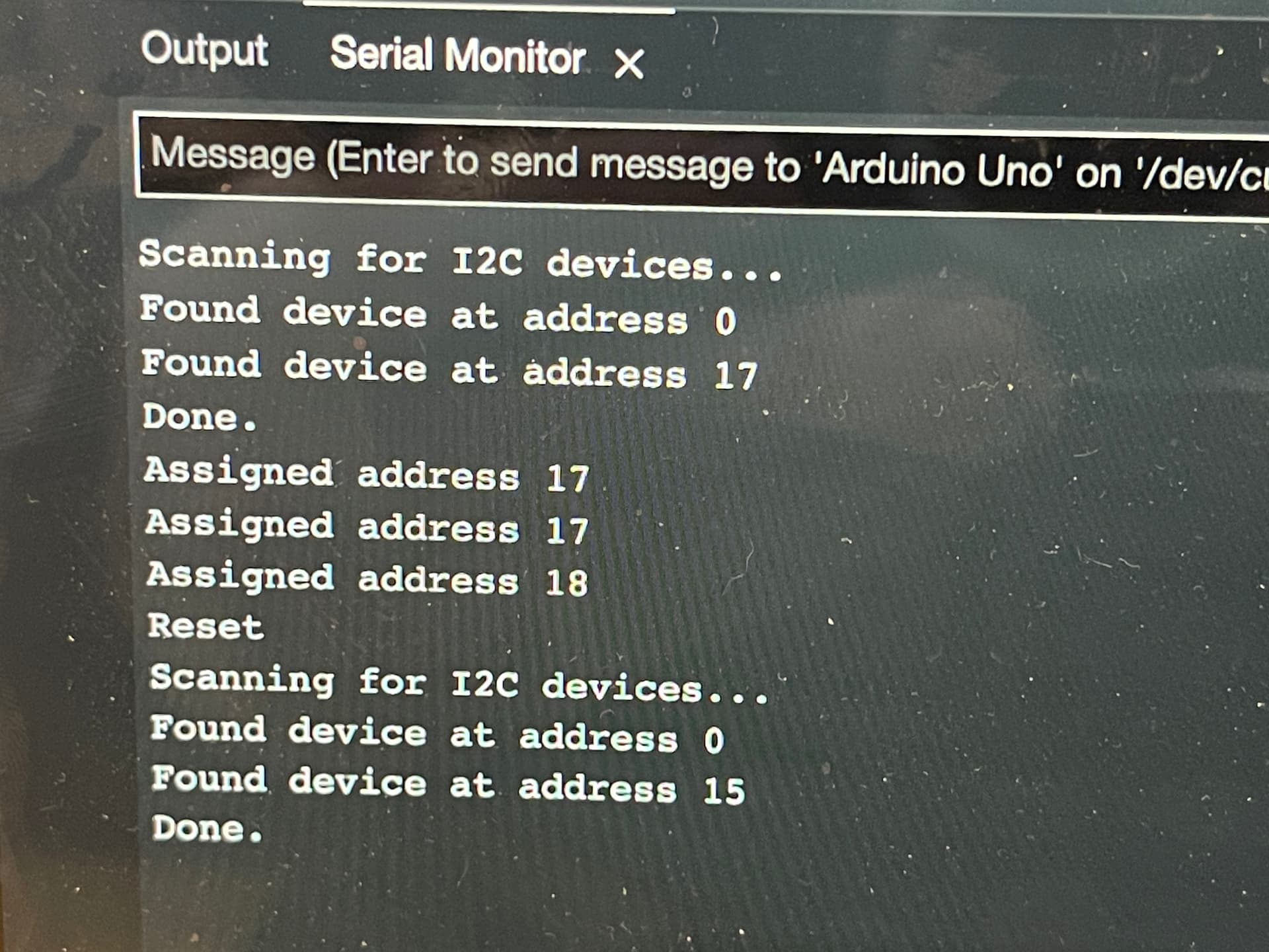
This is the seti2c on a new arduino same shield. Ran the command a17 twice after scanning. Then just an alone. After that did a reset and scan.

I ran the seti2c again using a different Grnd for connection to jmp1 and got a different result this time. Also did not assign my own address but instead entered just “a” then “r” afterwards.
The I2C default address used by our Motoron library is 16, not 17, so that explains why you have been having trouble with the example programs.
Can you run the sketch again to set the I2C address to 16? Send “a16” while the JMP1 pin is connected to ground, then remove the connection between JMP1 and ground when you are done. Be sure to reset or power cycle the Motoron while JMP1 is disconnected. Once you do that, can you retry the other examples?
- Patrick
This is running simple.ino. M3 light looks yellow in the video but it is red. Just want to clear it with you that everything looks proper.
The careful.ino has no output in the serial monitor when running now as well.
1 Like
The LED behavior from your Motoron looks good to me now!
- Patrick
Great! Thank you for all the help!
2 Likes