Hello,
I have M3S256 motor controller and I like the approach of using I2C instead of GPIO pins !
First everythting worked as expected, I was able to control motors using Arduino motoron library, using the default I2C address 16, all the leds on the Motoron working as described in the user guide. However suddenly controller stopped working and it appears that it has lost I2C address (16) totally. I have I2C scanner builtin in my sketch and no 16 address is shown. I have doublechecked that SCL and SDA wires are connected to my arduino A4,A5 pins. There is another I2C device (OLED display) working normally.
I have tried to ground the JMP1 pin, but no zero (0) address is present. Motoron board has yellow led on and red led also on (indicating some error. The red led was off when the board communicated normally. In my sketch:
getlasterror =50 and productid and firmware = 0. When I had connection product id and firmware reported positive values. What to do ? I have not tried to change I2c address, I think it woud not succeed, because the zero address is not visible in the I2C bus.
Help !
I am sorry to hear you are having problems with your Motoron M3S256. Could you post your I2C scanner program as well as some pictures of your setup that show all of your connections? Also, could you try the Motoron separately from the rest of your system (i.e. with no other I2C devices involved)?
By the way, it sounds like you’re a little confused on how the JMP1 jumper works. Just to clarify, address 0 is a general call address that the Motoron will respond to (whether or not JMP1 is connected to ground or not). When JMP1 is connected to ground, the Motoron will ignore it’s configured I2C address (16 by default) and use address 15 instead.
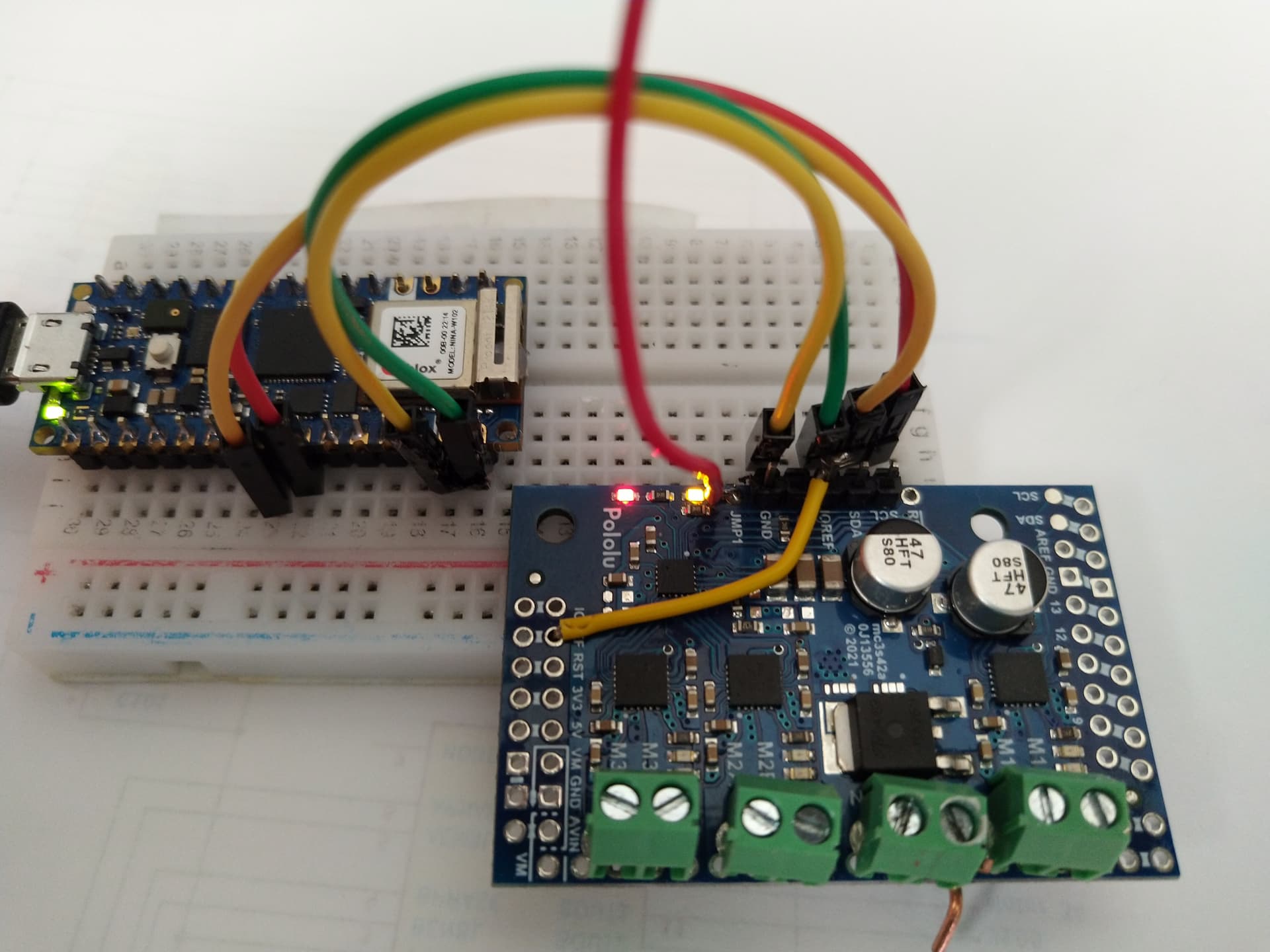
Here is my connections : Arduino RP2040 Connect and Motoron
GND , VIN to GND, IOREF and A4 to SDA, A5 to SCL. I have not connected the motor power here, but I have also tested motor power connect (no I2C address).
Note here: pin IOREF (green wire to VIN Arduino) is damaged, but I connected it to IOREF pin on the left (yellow jumper wire) and the yellow power LED is on. I have also tested the connectivity between A4 and SDA pin on the right side & A5 and SCL.
void i2cScanner()
{
  byte error, address; // variable for error and I2C address
   Serial.println("I2 Scanning... started");

  nDevices = 0;
  for (address = 0; address < 127; address++)
  {
    // The i2c_scanner uses the return value of
    // the Write.endTransmisstion to see if
    // a device did acknowledge to the address.
        Serial.print(address);
      Serial.println("  addr !");
    Wire.beginTransmission(address);
    error = Wire.endTransmission();

    if (error == 0)
    {
      Serial.print(address);Serial.print(": ");
      Serial.print("I2C device found at address 0x");
      if (address < 16)
        Serial.print("0");
      Serial.print(address, HEX);
      Serial.println("  !");
  //    i2address[++i]=address;
      nDevices++;
    }
    else if (error == 4)
    {
      Serial.print("Unknown error at address 0x");
      if (address < 16)
        Serial.print("0");
      Serial.println(address, HEX);
    }
  }
  if (nDevices == 0)
    Serial.println("No I2C devices found\n");
  else {
    Serial.print(nDevices);
    Serial.println(" found\n");
  }
}
It looks like you might have just stabbed the header pins through the Motoron pins instead of soldering them; is that the case? If so, please note that you will need to solder them to the board to ensure a good electrical connection. If you are new to soldering, I recommend Adafruit’s Guide to Excellent Soldering. Also, you should probably connect the IOREF pin to the 3.3V pin on your RP2040 instead of VIN.
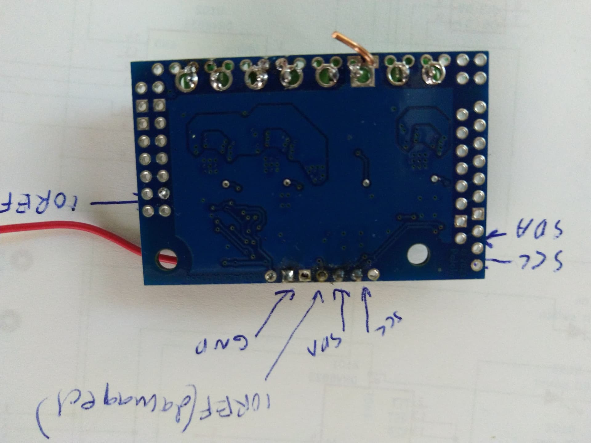
If it still does not work after soldering, could you post updated picture of your setup, as well as close-up pictures of both sides of the Motoron board that show the soldering on the header pins and terminal blocks?
Here is the image on the backside of the board. All pins are soldered, except the damaged IOREF, this connection was restored using the other IOREF pin. The documentation says that logic voltage should be between 3.0-5.5V, RP2040 VIN has about 4.5V powered via USB. Originally Motoron is installed on my custom PCB and it is powered using Lipo 3S via L7805 voltage regulator giving about 4.8V (and it was working with this configuration).
Yellow led is on, so power should not be the problem.
Also as I mentioned earlier when I measure the connectivity between A4,A5 pins the unsoldered SCL,SDA pins,this is ok. Proving that I2C wires should be good.
Is it possible that the IC on the board has lost the program ? Is it possible to reboot/reset the board somehow ? I have also read about pullup resistors are needed on the I2C bus, are those resistor on the board, could I add some external pullups, if so how to do it ?
Have you the schematic of this board, this could help to understand what is going on here.
We do not release schematics for the Motoron controllers. The I2C pins on the M3S256 are pulled up to IOREF, so the IOREF pin should be powered with the same voltage that you are using for your logic signals. Since the RP2040 uses 3.3V signals, you should power it with 3.3V. Why do you think the IOREF pin was damaged on your board (i.e. how did you test it)?
I am a little confused by your picture. From the angle it is hard to tell if anything is actually soldered to the pins, but if you soldered the header pins with the long end going through the top of the board, they probably are not long enough to make proper connections in your bread board (especially with the solder on the bottom-side as well). The intended orientation is shown in this picture from the product page. Please note that even with the LED lit and your multimeter showing continuity, there could still be intermittent connections causing problems. Also, I recommend adding more solder to the terminal block pins (preferably, the solder should fill the hole).
You can test whether or not the microcontroller on the Motoron is damaged by first removing all of the connections and then only supplying GND and logic power (IOREF). If it is still functioning correctly, you should see the yellow LED blink 4 times quickly and then begin blinking slowly.
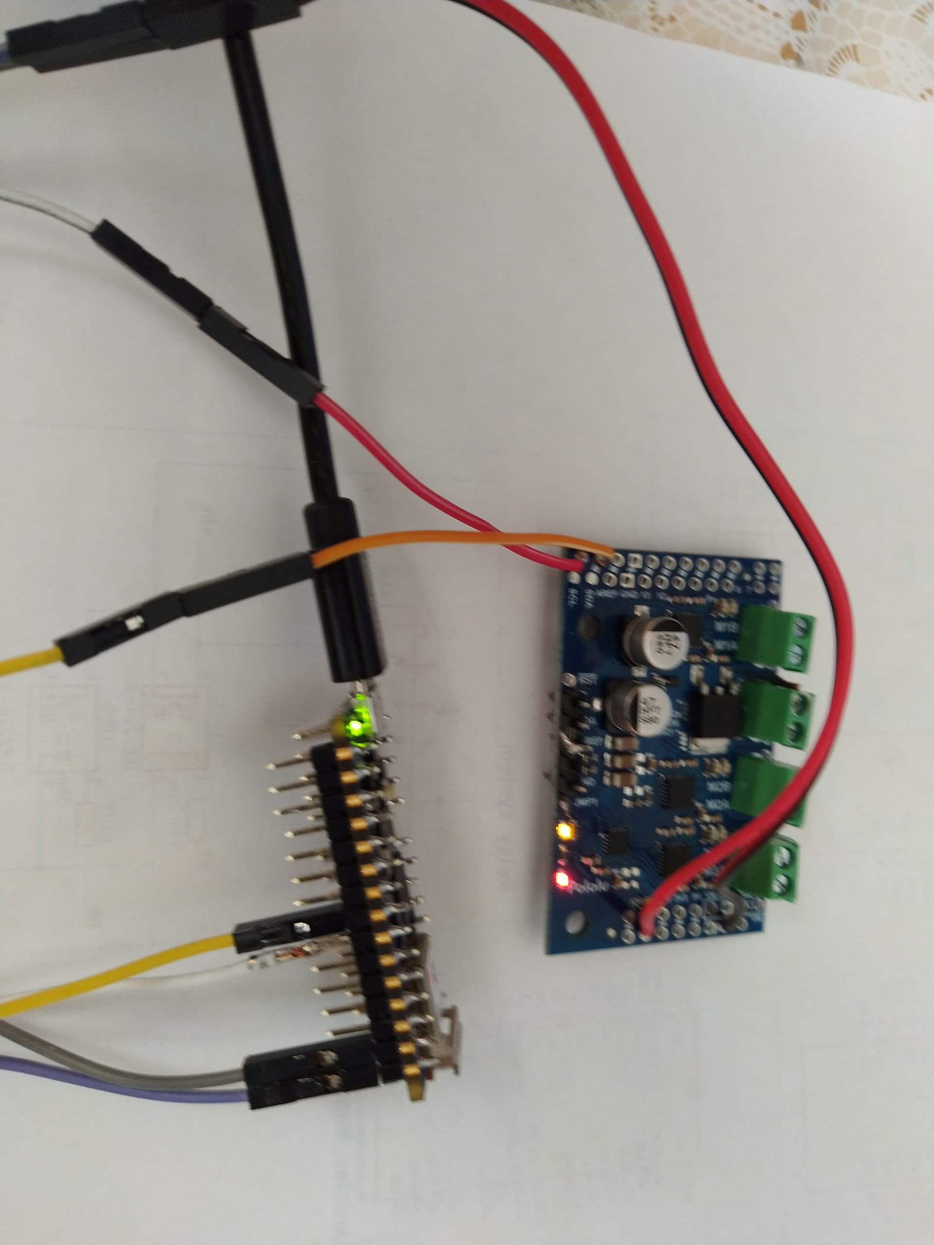
I decided to reconnect everything. GND,IOREF SDA,SCL as shown in the image. But no I2C address. The same is true whether I connect IOREF to 3.3V or VIN in the RP2040.
When SDA,SCL are disconnected, connecting power: yellow and red LEDs are immeadiately on, no blinking.
RP2040 is not damaged, because it can connect for example OLED via I2C normally.
The original IOREF pin got damaged when I tried to push the Motoron to my PCB and the pin popup. The was tiny copper part from the board in the pin. The SDA pin is close to IOREF, could it be damaged too ? However the board is not working using the other SDA pin. I understand that your design data is not publically available, but can you check this from PCB design, if this could cause the board failure ? There are no visible signs of burns in the board.
Unfortunately, if the yellow LED stays solidly lit at power up instead of doing the blinking pattern I described, the microcontroller on the board was likely damaged. It is not entirely clear to me what happened from your description, but if it was working before that incident and isn’t now, that incident could have been the culprit.
If you would like to try again with a replacement, please email us at support@pololu.com with a reference to this thread and your order information, and we can look into how we can help you out.