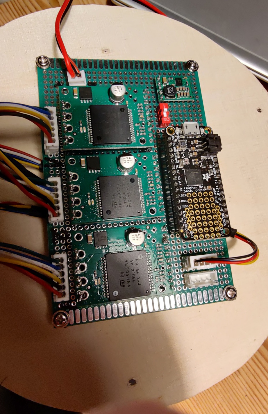
I use an Adafruit Feather M0 (SAMD21G) to generate the PWM signals. By default the pwm frequency is 730Hz. When i drive the motors at 25%, 50%, 75% duty cycle all motors behave very similar and have a very similar speed at each tested duty cycle.
Since the sound is very noise at this frequency i increased the pwm frequency to 19.2 kHz. However, now two of the three motors behave similar (rotate at same speed) while 1 motor approximately rotates at half that speed. This behaviour occurs at 25%, 50% and 75% duty cycle, respectively.
When i switch the motor driver and thus the pin settings and timer setting, it is always the same motor that rotates much slower than the other 2. I am very confused, since this only happens at 19.2 kHz and not at 720Hz.
Does anybody know the reason for that behaviour? Are there different generations of the motors? (all bought simultaneously)
That behavior is extremely unusual. Can you post some pictures of your setup along with more information about it like what your power supply is, how much load is on each of your motors, and how you are measuring their speed? Are there any differences in how you have used your three motors so far?
Could you also look at what the driver outputs connected to the problematic motor are doing with an oscilloscope and post screen captures of that?
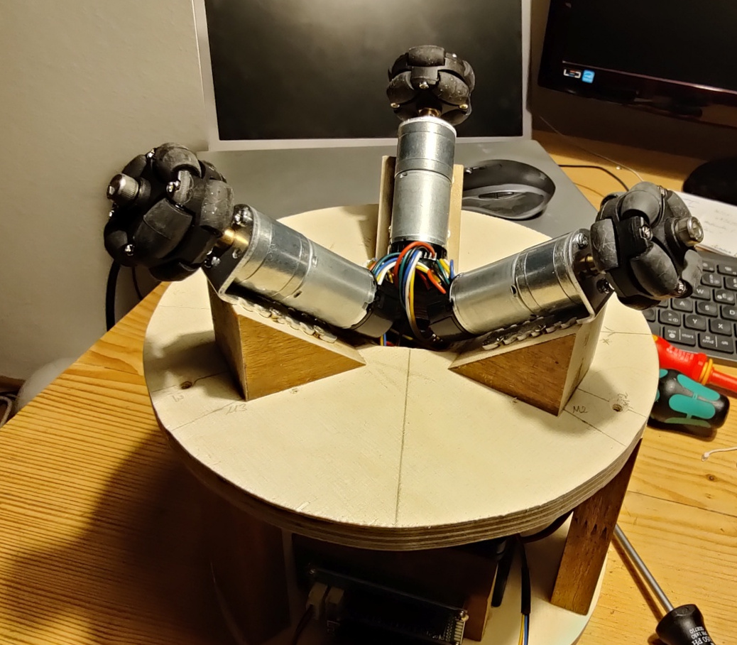
first, thank you all for the help! I am building a robot which balances on a ball. The power supply
is a Bosch Li-Ion battery pack (18v) (4.0Ah ) but i restrict the output voltage to 12V (for tests i went up to 13.5V). I don’t think this could have damaged the motors.
I estimate the maximum load to be roughly 50% of the load before the motor stalls. However, when i want to rotate at very low speed the motor stalls for a short moment before the PI controller increases the duty cycle sufficiently to get the motor started. But for the tests i made and all mentioned results, there is no control loop i just set a specific pwm duty cycle and measure the speed. Speed is measured using the attached encoders, but the differences between motor 1 and motors 2,3 are easily visible by looking at the wheels.
The motors are brand new and have used them just for these initial tests. All motors are marked with RK-370SD-22140 DC/12V 180905. I checked that the differences also occur when the gear box is removed. Visually and by weight they are all identical.
Unfortunately, i dont own a oscilloscope, only a multimeter. Here are the outputs of some tests. I used one motor driver and just swapped the motors all the time. But i can reproduce the results using the other vnh5090 motor drivers. Here, the speed is measured by the encoders, the pwm freq is the one calculated (but i see same frequency using multimeter measurement) and voltage is the measured DC voltage with the motor attached and spinning.
Are the drivers socketed? What happens if you physically switch the drivers around but keep everything else the same; does the problem still stay with the motor?
Getting to the bottom of this will probably require looking at your setup with an oscilloscope so you can actually see what is going on. Is there any way you can get or borrow a scope? Even aside from the current need, we strongly recommend investing in scope. You can get a decent one these days for a few hundred dollars and it will save you a lot of time and give you better understanding of your systems, which enables better designs, better margins of operation, etc. Without one, you are left mostly just guessing about what might be happening, which is not a great way to operate.
Also, when you say you have only used your motors for these initial tests, what exactly does that mean? Have you only tested them as shown in your pictures, i.e. with just the wheels attached and no other loads applied? Please keep in mind that running the motors at 50% of their stall torque at their nominal voltage is too much load for them. It might be okay for transient intervals, but the motors drawing too much current for a sustained period could result in thermal damage to the motor windings and brushes, so a general recommendation for brushed DC motor operation is around 25% or less of the stall current at their nominal voltage.