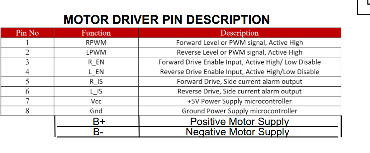
Hi, I am using the metal gear motor Item 4845, High Power 12V, gear ratio 47:1 with Mbed Microcontroller. I am also using the driver HW-039 with the motor. I am using a simple PWM to operate the motor but I found out that the motor does not rotate below 45% PWM. I am using a simple PWM library using Mbed with the range -1 to 1 which can be found here:
I am also using a Power adapter of 12V, 5000mA rated output.
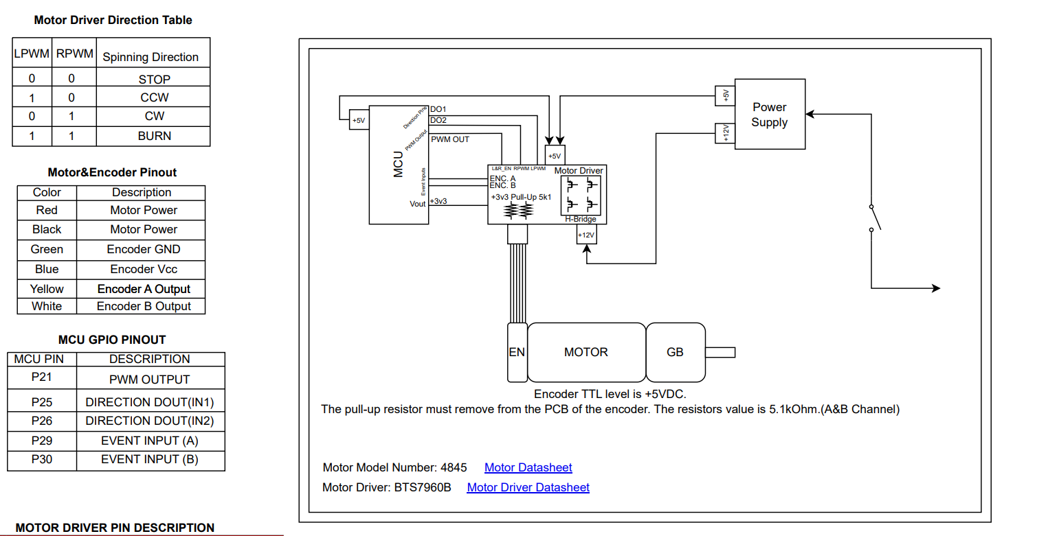
I am using the pwm pin 21 on Mbed and pins 25 and 26 as direction pins.
How is it possible that my motor operates (without any load) with PWM values greater than 0.45? I am using a PWM period of 1kHz, changing the period to 25kHz makes little difference, although the voltage output at every pwm values increases as we decrease the PWM period.
Hello.
To rule out any possible issues with your setup, can you try hooking up your motor directly to a benchtop adjustable power supply to check its startup voltage? Set the current limit high (ideally, 5A) and then slowly ramp up the voltage starting from 0V until the motor starts moving.
Also could you post some pictures of your connections?
- Patrick
Hi Patrick,
Thank you for your reply. We connected the Motor to a power supply and saw that the lowest Voltage at which the motor would spin was 1.2V.
I am posting our Circuit diagram here. The PWM range that we are working with is from -1 to 1 as specified in the library. We also tried different period for the PWM signal ( 0.00004s - 0.002s). As we increased the period, we noticed that the motor output voltage for a specific PWM increased (for eg at a period of 0.00004s, the motor output at 67% PWM was 8.7V, at a period of 0.001s, the motor output at 67% PWM was 10.9V). For this period range we tried, we noticed that Motor would start moving above 37% PWM for 0.00004s and for an input below 37% PWM, the motor would output very low voltage (in the range of 0.1V to 0.3V).
It sounds like your motor is behaving the way we would expect it to when you hook it up directly to your power supply. If it runs at 1.2V, that suggests it should run at duty cycles to as low as around 10% when you power it from an adequate 12V supply.
Since the motor is probably okay, it is likely that the behavior you are seeing is caused by some other part of your system not behaving the way you expect it to. I am not that familiar with your other hardware, but one possibility that might help explain the variation in results with different PWM frequencies is your driver might have relatively high switching times. So, at high frequencies the driver might be spending a significant duration of what you expect to be high time in a switching state. If you want to understand the issue better and isolate where it is coming from, I would suggest looking at your setup with an oscilloscope so you can actually see what is going on.
- Patrick
Thank you Patrick, I will hook up the motor with an oscilloscope to see the Motor driver behaviour.
I made some more tests with reducing the switching frequency even further and when I reduced it to 50Hz, I was able to get the motor moving at small PWM values. The motor voltage reading was as follows (PWM range is -1 to 1 where PWM of 1 corresponds to maximum speed in clockwise direction and PWM of -1 corresponds to maximum speed in anticlockwise direction):
50Hz switching frequency:
0.098 PWM - 7V
0.37 PWM - 11.3V
1 PWM - 12.1V
This is unexpected behavior as a PWM 0f 0.098 should not be running at 7V.
100 Hz switching frequency:
0.098 PWM - 0.662V (motor does not move)
0.16 PWM - 8.7V
0.37 PWM - 11.1V
1 PWM - 12.1V
Additionally at higher Frequencies, we could see the current output to the motor as alternating from a low value (almost 0A) to the required value. Is this normal behavior as well? because I think the problem might be that the current is switching at a very high rate at higher frequencies.
I think at this point it is probably not worth it to speculate about what your system is doing based only on your multimeter measurements; looking at it with a scope should give a much better picture of what is going on. Keep in mind that what a multimeter reports is going to be based on some type of averaging, which presents plenty of opportunity for it to give misleading results when you use it for something like this where you are varying the duty cycle and frequency for a square wave signal.
- Patrick
Hi Patrick, Thank you for your feedback.
You are right about the multimeter giving average readings for the voltage and current but those are what we want to actually check since PWM is just average motor voltage output.
Moreover, when we checked the motor driver output PWM voltage with the motor disconnected, we noticed accurate readings (6V at 0.5 PWM, 9V at 0.75PWM and so on) but when we connect the motor, the voltage reading somehow jumps to a higher value with the same PWM output. What can possibly be happening that when we connect the motor, the voltage output for the same PWM increases?
As I mentioned already, your multimeter measurements may not reflect the true behavior of the system. Until you look at the setup with a scope, we can only guess about what might be happening. I do not think it is useful speculate on a cause until you know how your system is behaving, and having feedback from a scope will save you a lot of time understanding how modifying parameters like the signal frequency and duty cycle really affect your system.
- Patrick
Hi Patrick,
Thank you for your help and your replies.
I wanted to update that we hooked up the motor to use a PID loop (close loop) so that we were getting encoder readings as feedback. We were giving a velocity as setpoint and using the encoder data to calculate the velocity as a process variable. Tuning the PID parameters allowed us to use the motor at much lower PWM values.
1 Like
I am glad to hear you have been making progress with your project! Thanks for updating us.
- Patrick