
I am using this motor with the Hall Effect Encoder included.
I am using a STM32 uC that requires (or at least recommends) 3.3V-level input for GPIO/External IRQ. I tried to take the 5V output of the motor encoder and use a 400Ohm/600Ohm voltage divider circuit to make the input effectively 6/10*5V=3V (which is close enough to 3.3V according to the STM32 datasheet.
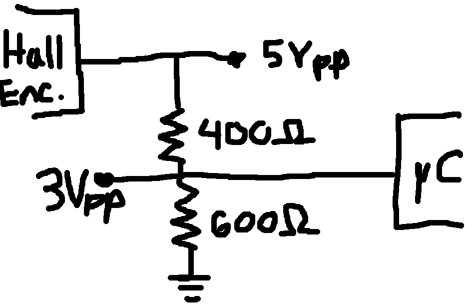
What I’m seeing on my oscilloscope is a square wave of the correct frequency, but only .5Vpp. I was treating the square output pin of the Hall Effect encoder as a 5V voltage source. I am guessing this cannot be done, so I’m wondering if I could get some info as to what circuitry is in the encoder and how you would best recommend changing the voltage level to something lower?