Motor does irritating sounds

Hey there :slight_smile:
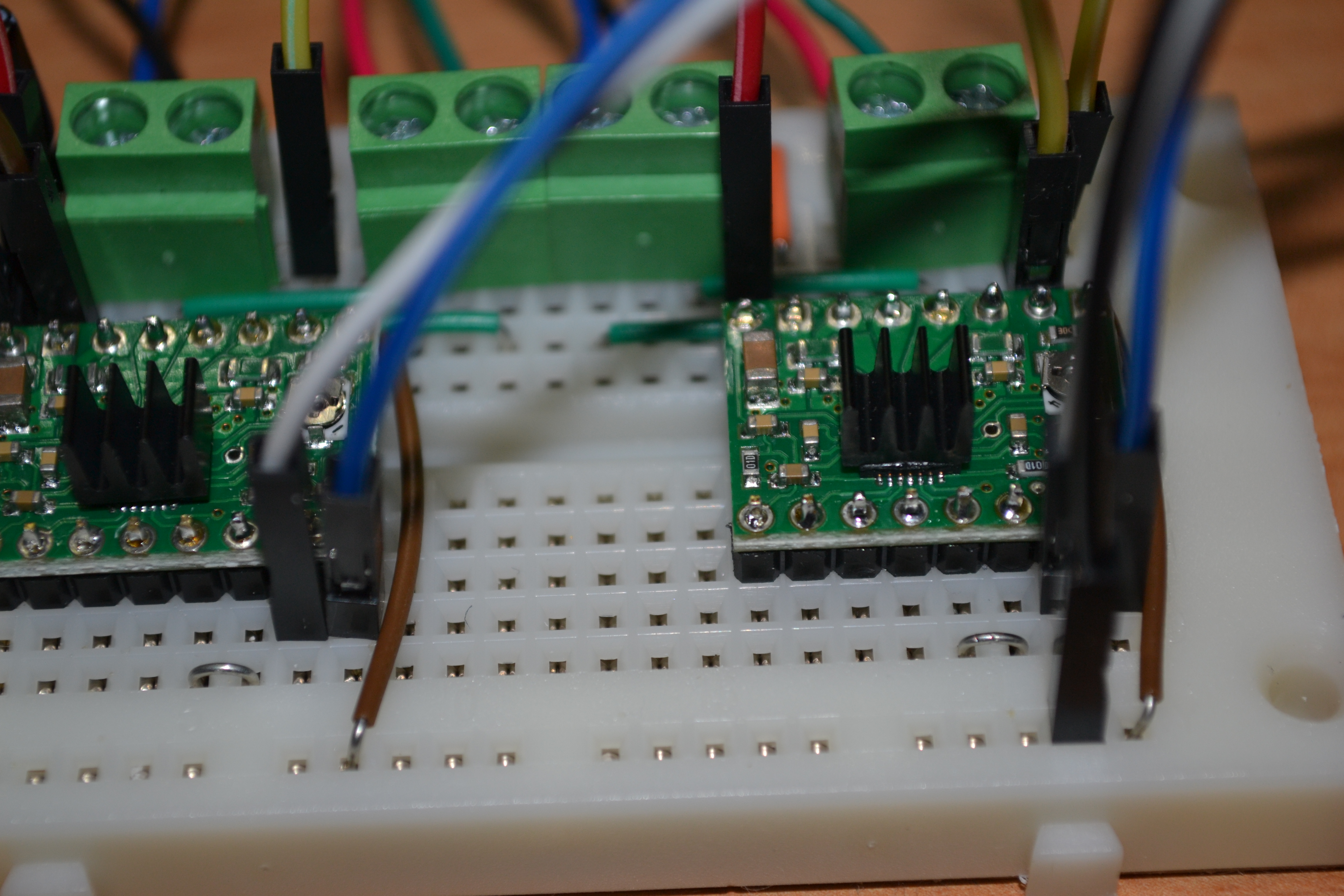
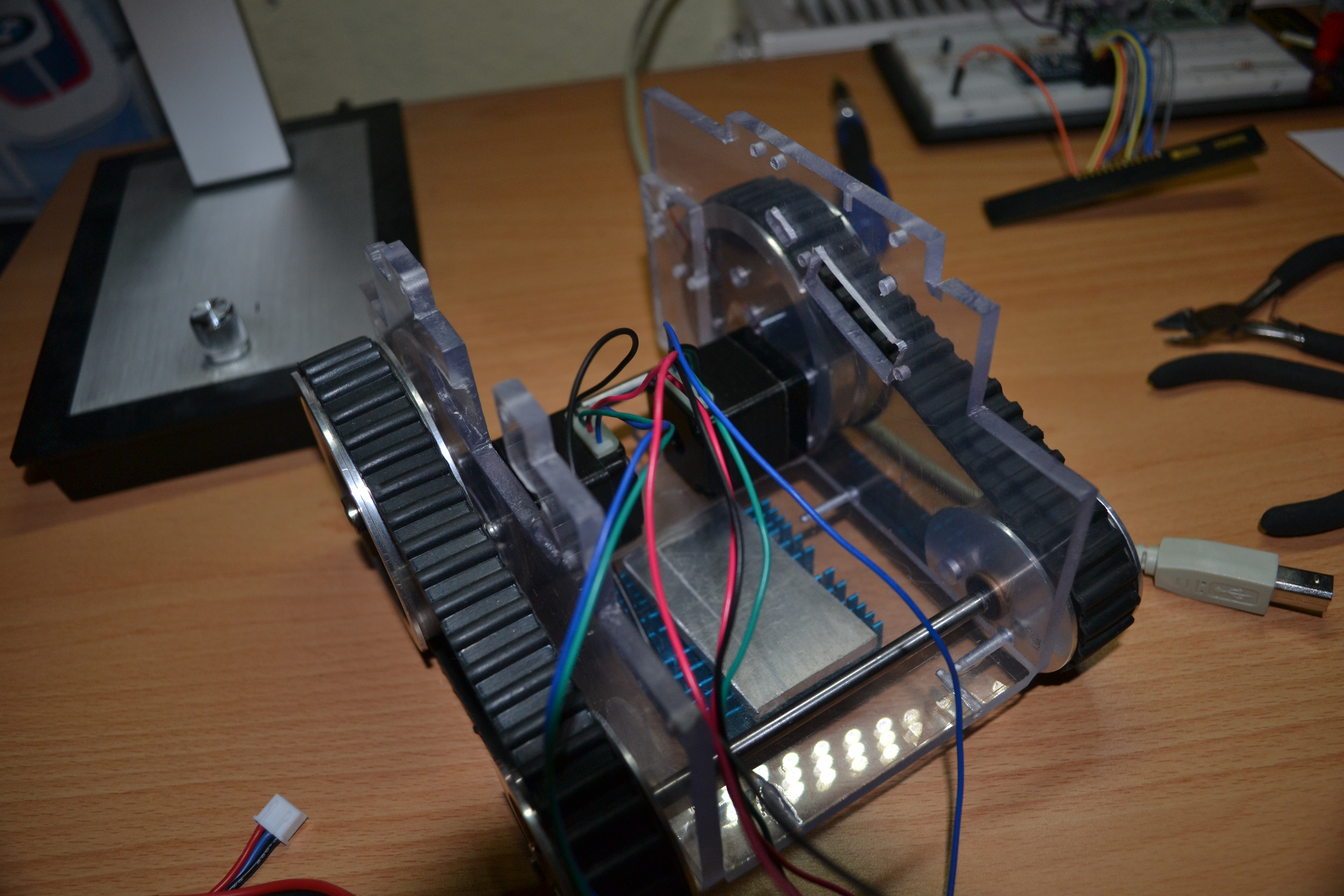
I bought the a4988 driver a couple of weeks ago and got it running with the following motor:
https://www.pololu.com/product/1205
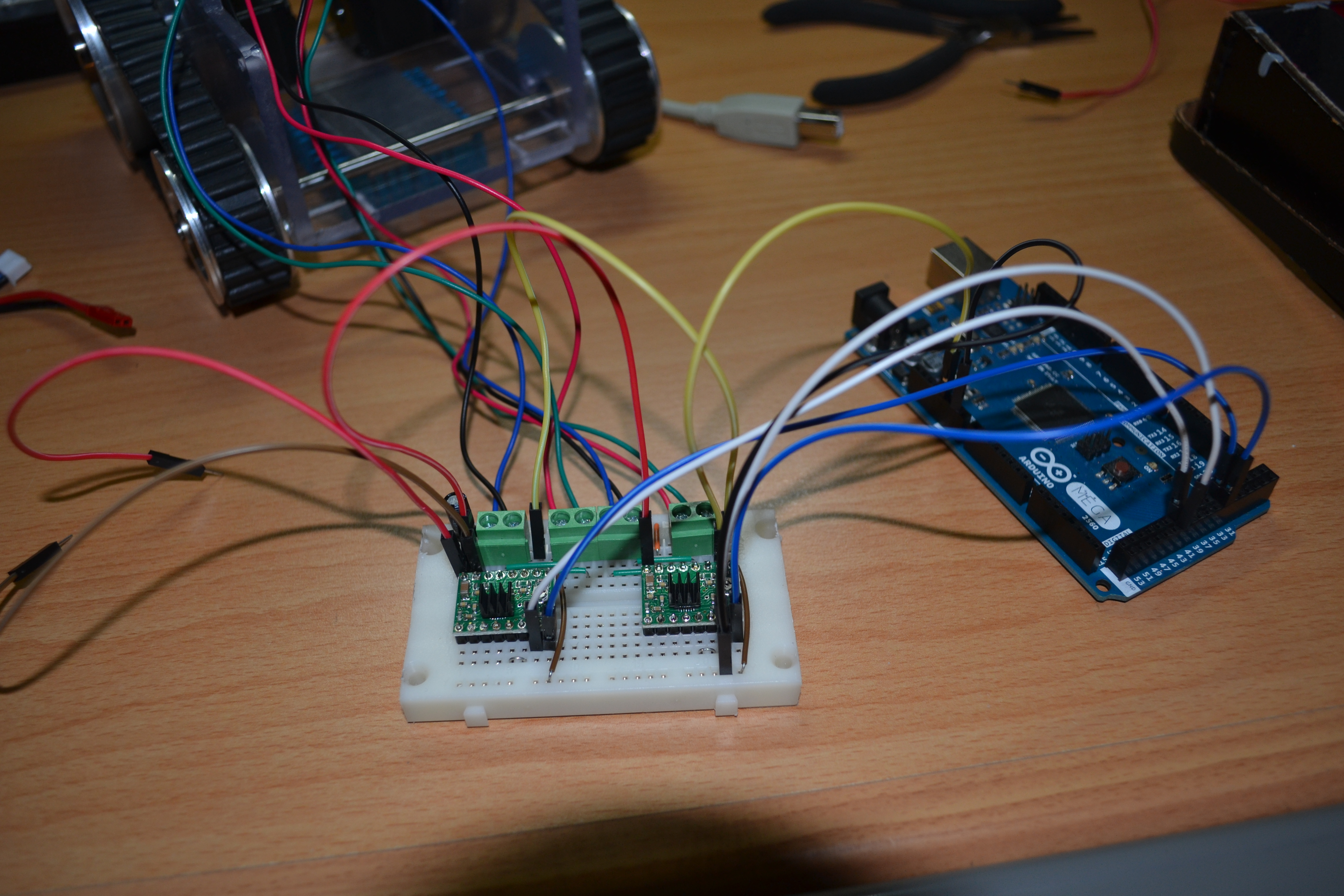
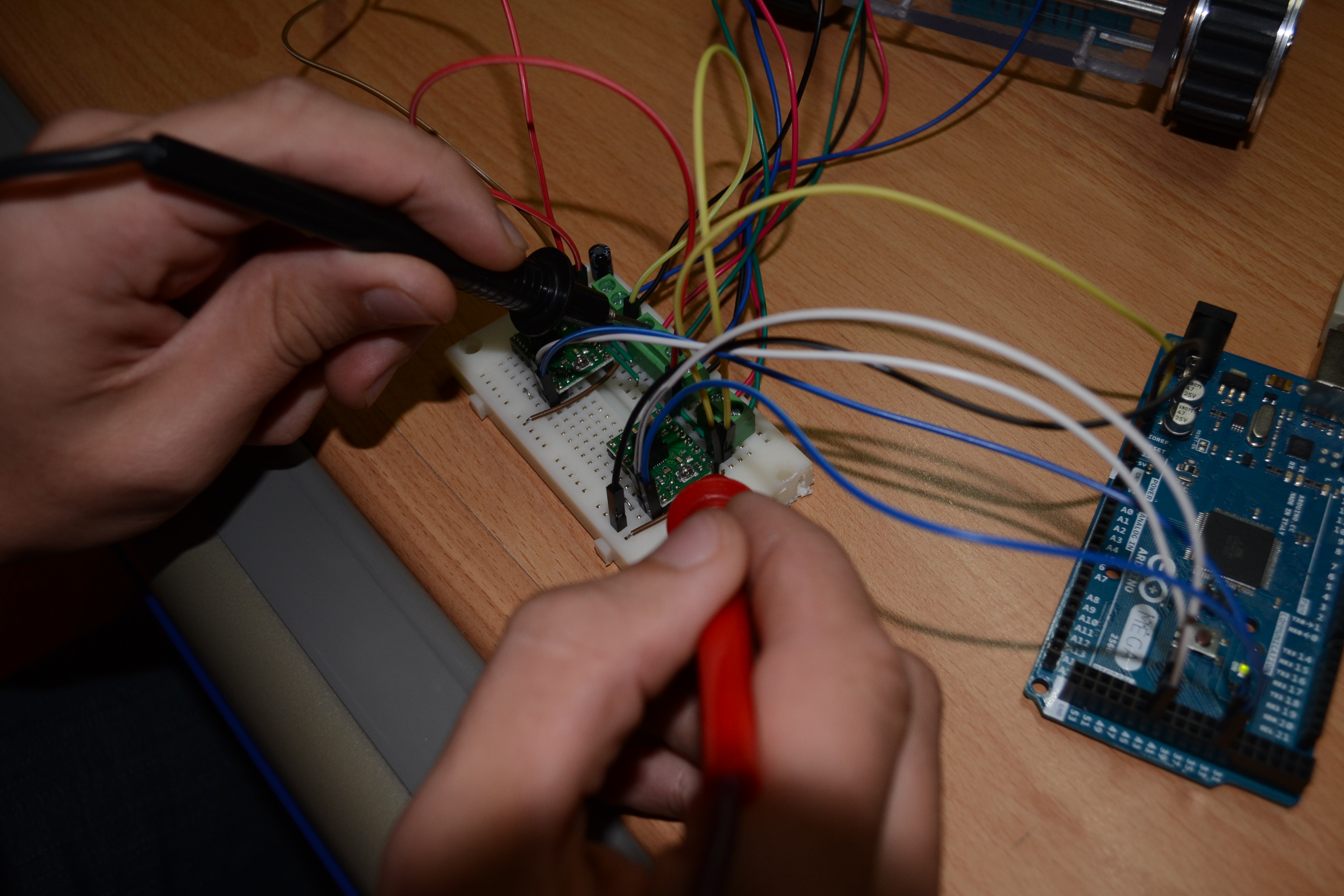
I connected it in minimal setup with my Arduino MEGA, my code is the following:

[code]//simple A4988 connection
//jumper reset and sleep together
//connect VDD to Arduino 3.3v or 5v
//connect GND to Arduino GND (GND near VDD)
//connect 1A and 1B to stepper coil 1
//connect 2A and 2B to stepper coil 2
//connect VMOT to power source (9v battery + term)
//connect GRD to power source (9v battery - term)

int stp = 42; //connect pin 13 to step
int dir = 32; // connect pin 12 to dir
int a = 0; // gen counter

void setup()
{
pinMode(stp, OUTPUT);
pinMode(dir, OUTPUT);
}

void loop()
{
if (a < 800) //sweep 800 step in dir 1
{
a++;
digitalWrite(stp, HIGH);
delay(3);
digitalWrite(stp, LOW);
delay(3);
}
else
{
if (a<1600) {
digitalWrite(dir, HIGH);
a++;
digitalWrite(stp, HIGH);
delay(3);
digitalWrite(stp, LOW);
delay(3);
}
if (a>1600) //sweep 800 in dir 2
{
digitalWrite(dir, LOW);
}
}
}[/code]
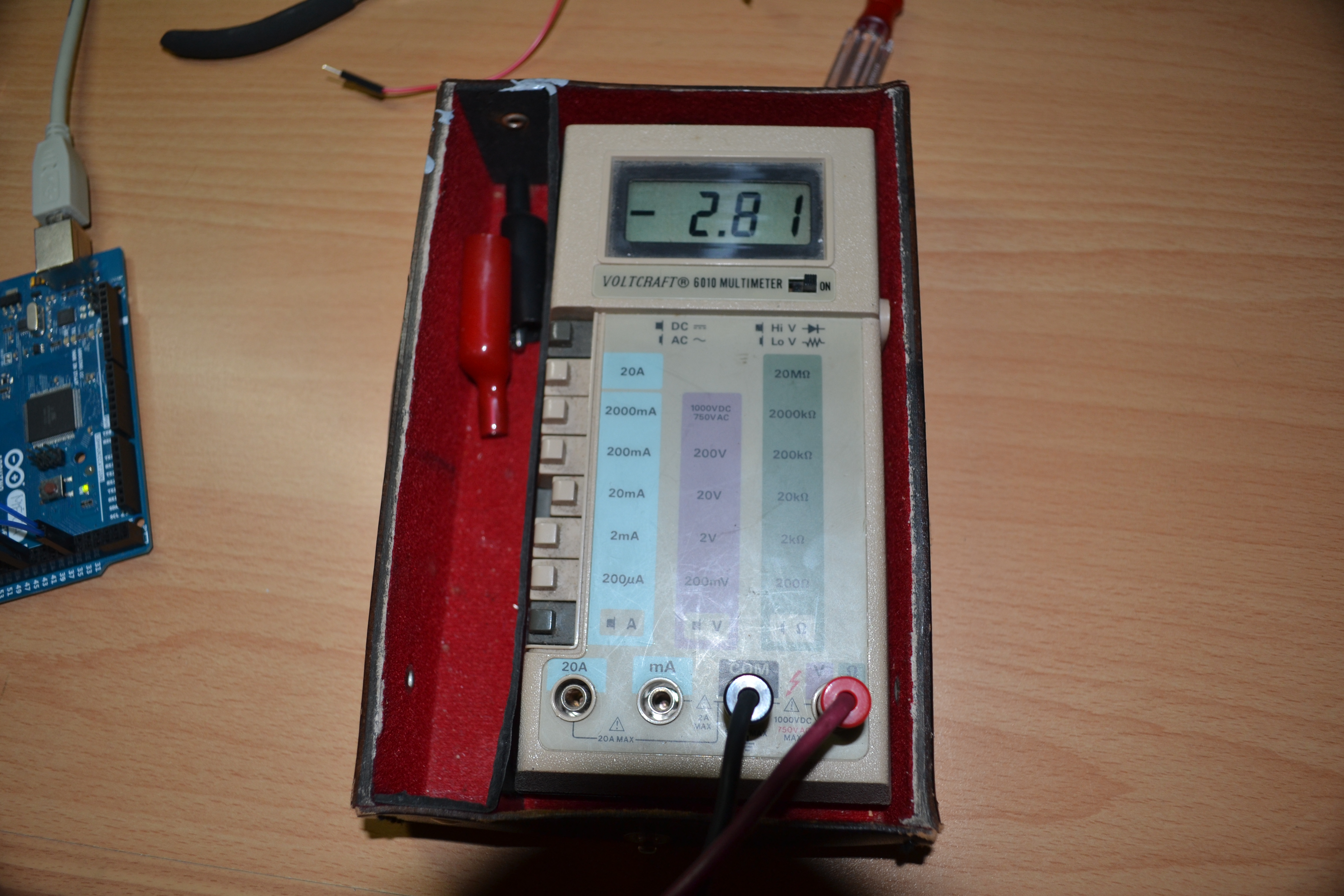
It is powered with 22.2V from three 7.4V Batterys.

However, after rotating the given 800 steps in one direction and backwards after that, It does stop to move but also does irritating sounds. Is that because of the minimal setup or because of the program?

Greetings and thanks in advance,
joelsa

Hello, Joelsa.

Have you set the current limit on your stepper drivers? This blog post has a nice video that shows the proper way to do this.

To be honest, your code is not the cleanest. It looks like the if (a>1600){} block will never execute because your only a++; statements are in the blocks where a has to be less than 1600. So once a=1600, it will no longer change and will never be greater than 1600. However, I do not see anything in there I would expect to cause the stepper or driver to make an unusual noise.

It is normal for stepper motors and drivers to make some noise. If you have the current limit set, could you post a video of the noise here so we can see if there is anything unusual? Also, the comments about a “9v battery” in lines 7 and 8 of your code do not match your description of “22.2V from three 7.4V batteries”. Could you show how you are powering the stepper driver in your video as well?

-Nathan

Sadly I got no camera at the moment and my phone camera is nearly unuseable. I will try to get a camera of a friend and then upload a video/images.

Hello,
I now got a camera and uploaded a video below.
Yes, I set the current limiting resistor to something between 0.25 and 0.30, which should be more than low enough.
I changed my code to something cleaner I found on the arduino forum, as this code waits between pulling the STP high and low, which seemed more beautiful to me.

// testing a stepper motor with a Pololu A4988 driver board or equivalent
// on an Uno the onboard led will flash with each step
// as posted on Arduino Forum at http://forum.arduino.cc/index.php?topic=208905.0

byte directionPin1 = 32;
byte stepPin1 = 42;
byte directionPin2 = 33;
byte stepPin2 = 43;
int numberOfSteps = 200;
byte ledPin = 13;
int pulseWidthMicros = 1000;  // microseconds
int millisbetweenSteps = 9; // milliseconds


void setup() 
{ 
  Serial.begin(9600);
  Serial.println("Starting StepperTest");
  digitalWrite(ledPin, LOW);
  
  delay(1000);

  pinMode(directionPin1, OUTPUT);
  pinMode(stepPin1, OUTPUT);
  pinMode(directionPin2, OUTPUT);
  pinMode(stepPin2, OUTPUT);
  pinMode(ledPin, OUTPUT);
  

  digitalWrite(directionPin1, LOW);
  digitalWrite(directionPin2, HIGH);
  for(int n = 0; n < numberOfSteps; n++) {         //200 in one direction
    digitalWrite(stepPin1, HIGH);
    digitalWrite(stepPin2, HIGH);
    delayMicroseconds(pulseWidthMicros);
    digitalWrite(stepPin1, LOW);
    digitalWrite(stepPin2, LOW);
    
    delay(millisbetweenSteps);
    
    digitalWrite(ledPin, !digitalRead(ledPin));
  }
  
  delay(1000);
  

  digitalWrite(directionPin1, HIGH);
  digitalWrite(directionPin2, LOW);
  for(int n = 0; n < numberOfSteps; n++) {         //200 backwards
    digitalWrite(stepPin1, HIGH);
    digitalWrite(stepPin2, HIGH);
    delayMicroseconds(pulseWidthMicros);
    digitalWrite(stepPin1, LOW);
    digitalWrite(stepPin2, LOW);
    
    delay(millisbetweenSteps);
    
    digitalWrite(ledPin, !digitalRead(ledPin));
  }
}

void loop() 
{ 
//nothing here, done just once in setup
}

I am now powering the motor through a single 7.4V Li-Po battery, I do not think that I need more than that.

As you can see in the following image, my soldering is not the very best, but I think its is ok.

Here you can see an image of my breadboard connections, although I checked everything multiple times.
I also mounted heatsinks on it, for security reasons. ^^

This is an image of my overall layout.

An image of my robot, so you can understand what I am trying to power.

The video showing powering and the sounds.
https://www.youtube.com/embed/DSUx_wE70lg
What I found interesting is, that even if the motors are not running, there are almost 3V going through the motors.


I know that It tries to hold torque, but at that moment there is nothing to hold for the motor.

Hello, Joelsa.

Thanks for posting those very clear pictures and the video. Those current limits seem about right for that stepper motor, and the driver should be capable of handling them as well. I listened to the audio in your video carefully and I did not here anything abnormal at the end of the video. It seems like you might be hearing a normal high pitched whine from the motor caused by the way the current limiting on the stepper drivers works. Instead of using a current limiting resistor, current limiting on these drivers switches the power to the motor coils on and off very quickly like a switching regulator. The switching frequency is generally above the threshold for human hearing, but if you are young or have good hearing, it might still be audible.

The voltage on the motor leads you are noticing is also what I would expect. The current is required for the holding torque you mention and it runs through the coil, even when stationary with no torque. The motor you mentioned in your first post (#1205) is rated for 3.5V at a current limit of 670mA, so 3V seems about right with you running them a little bit under their current limit. If you want to turn off the current to the motors when you are done moving them, you can look at using the sleep or enable pins, which are discussed in the datasheet for the A4988.

I notice that you only have a single electrolytic capacitor in the corner of your breadboard for the motor power supply. You might try to place separate capacitors like that on the breadboard at the power inputs for the two stepper drivers. In general, this can help avoid LC voltage spikes, which could damage the board, and it’s possible that some inductance in the system is causing some harmonic that is making the typical switching whine slightly more audible.

-Nathan

Hello nathanb,

Thank you for your fast and detailed answer.
I am pretty relieved that you consider this as normal.
Yes, I am quite young, I will ask some older people if they can hear it too. :smiley:
Adding a second capacitor actually made it quieter, that’s a good start.
I will use the sleep pins, but I will not need them in my final application. (This project here is more or less just a proof of concept)

Greetings
Joel