Motor chatters while program resets

1205 Stepper motor, A4988 Stepper Motor Driver Carrier:

After my program is uploaded to the Arduino, every time I hit the reset button or click on the Opens the serial monitor icon in the upper far right , the motor chatters for about 12 seconds while the program is set up. As soon as the program starts, the chatter goes away. The other stepper motor, with different board does not make noise.

The program does some other things and gets to the enable command for the stepper motor. This happens quietly as it waits for instructions to run the stepper motor. Everything runs great and runs quietly or sounds normally as the program runs enables and disables, runs the motor and stops it. The program runs, finishes and restarts with no chattering, over and over again but when I reset, I get the same chatter.

Is there something that I can do about that?

I have a 1205 Stepper motor and a Pololu item 1183: A4988 Stepper Motor Driver Carrier with Voltage Regulators, hooked to an Arduino Mega 2560 and it all works fairly well. I have a 30V 5W adapter as a power source.

Hello.

It sounds like the Arduino is doing something with the step or enable line when it’s coming out of reset. Does the problem still happen if you use different I/O lines? Can you post the simplest version of your program that demonstrates the problem (e.g. if you load a program that’s just an empty setup() and loop(), does the stepper motor still chatter after reset)?

- Ben

Upon testing for some pruned down code, I found that when I hit the reset button on the arduino board, the chatter only lasts for about 2 seconds. When I click on the Opens the serial monitor icon, it chatters for the full 12 seconds. I guess there is some communication between the computer and the arduino that takes more time.

I found that if I compile and upload “BareMinimum” from the example menu, it chatters but does not stop.

void setup() {
  // put your setup code here, to run once:

}

void loop() {
  // put your main code here, to run repeatedly: 
  
}

“Raise the Boom”
The “Boom” is a 17 inch long, light weight rack and pinion on a vertical slide rail.

This worked like the bigger program. It just raises the boom and then turns off the board to let the boom drop. I think that there is some additional code that is supposed to lower the boom in a controlled manor but it must be bypassed.


#include <Stepper.h>

#define stepPin 22
#define dirPin 24
#define enablePin 26
int raiseTheBoomSteps = 620;   // 675
int lowerTheBoomSteps = 200;

void setup()
 { 

  Serial.begin(9600);                              // initialize the// Serial port
  pinMode(stepPin, OUTPUT);
  pinMode(dirPin, OUTPUT);
  digitalWrite(enablePin, HIGH);
  
void loop() 
{ 
int j;
int accelerate = 5000;
digitalWrite(enablePin, LOW);
// Set the enablePin low so that we can now use our stepper driver.
// digitalWrite(enablePin, LOW);
// wait a few microseconds for the enable to take effect
// (That isn't in the spec sheet. It was just added it for sanity.)
delayMicroseconds(2);
digitalWrite(dirPin, LOW);                         // we set the direction pin in an arbitrary direction.

Serial.println("UP");
  for(j=0; j<=raiseTheBoomSteps; j++)
  {
    //Serial.println(j);
     digitalWrite(stepPin, LOW);
     delayMicroseconds(2);
     digitalWrite(stepPin, HIGH);
     delayMicroseconds(accelerate);
        if(accelerate >= 1024)
        {
        accelerate = (accelerate - (accelerate/199));
        }
  }
 delay(500);
 //digitalWrite(enablePin, HIGH);
 Serial.println("DELAY");
 delay(1000);


int k;
int decelerate = 5000;
digitalWrite(enablePin, LOW);
// Set the enablePin low so that we can now use our stepper driver.
// digitalWrite(enablePin, LOW);
// wait a few microseconds for the enable to take effect
// (That isn't in the spec sheet. It was just added it for sanity.)
Serial.println("DOWN");
delayMicroseconds(2);
digitalWrite(dirPin, HIGH);                          // we set the direction pin in an arbitrary direction.

   for(j=0; k<=lowerTheBoomSteps; k++)
     {
      digitalWrite(stepPin, LOW);
      delayMicroseconds(2);
      digitalWrite(stepPin, HIGH);
      delayMicroseconds(decelerate);
       if(decelerate >= 1024)
         {
         decelerate = (decelerate - (decelerate/199));
         }
     }
digitalWrite(enablePin, HIGH);
 Serial.println("DELAY DOWN");
 delay(5000); 
}

Given that the problem exists with the “bare minimum” Arduino program, that should be your starting point for debugging.

Does the problem still happen if you use different I/O lines?

Can you list how you have everything connected and post a picture of your setup?

- Ben

I got the same results.
I changed the pin call-outs from:

#define stepPin 22
#define dirPin 24
#define enablePin 26

to

#define stepPin 42
#define dirPin 44
#define enablePin 46

It sounds like maybe you aren’t following what I’m asking you to do. Can you physically change the pin connections you are making between your stepper motor driver and Arduino and see what happens when it is running the bare-minimum program? (Just to be clear, by “bare minimum”, I mean a program that contains nothing other than an empty setup() and loop() function).

- Ben

Do you mean to use different wires?

I think he means plug the wires to different pins on the arduino. You probably don’t need to change the wires.

I think he’s trying to make sure those pins are not faulty. It’s unlikely, but worth checking.

In general, I’ve had problems with chatter whenever I upload [this makes sense], but the problems in my main code are solved by very quickly declaring pinMode(pin,input); digitalwrite(pin,high); so that the step pins aren’t floating.

Make sure you don’t have any delays in the code before the void loop();.

Actually, if you can, just post all the code you have before void loop(). We know that it repeats the void loop fine, but it takes a bit of time in the first restart (which goes through void setup() and then void loop. For the rest of the time it’s just going through void loop.)

Looking back, I started by posting the original question. Then Ben asked me to show him pruned down code that still manifested the problem. In the third post (Wed Jan 09, 2013 8:35 pm), I added the “BareMinimum” program as well as some pruned down code below that.

If you look back there, I think that what you ask is in the pruned down code, although the code phrases are longer.

pinMode(stepPin, OUTPUT);
pinMode(dirPin, OUTPUT);
digitalWrite(enablePin, HIGH);

instead of what you suggest below;

pinMode(pin,input);
digitalwrite(pin,high);

I hope that that doesn’t cause a problem.

In the fifth post I indicated that I moved the pins from 22, 24 and 26 to 42, 44 and 46 but I got the same problem.
I will have to try to run the “BareMinimum” and the pruned down version with the new pin locations again when I get home from work.

Sorry, I have been thinking about this incorrectly. I was operating under the assumption that the board would be disabled until you did something with the enable pin (in which case, the behavior you are seeing is unexpected), but that is not the situation. It makes total sense that the board would chatter when the step, dir, and enable pins are floating, as happens when you are running the bare minimum program.

I don’t know what the bootloader is doing on your Arduino, but it sounds like maybe it is taking a while before your program starts running. The problem is that until your setup() loop runs, the stepper motor driver control pins are floating, which can lead to erroneous steps. One way to solve this is to put a pull-down resistor on the step pin so that you have a known, steady voltage on it whenever it is disconnected or connected to a floating input.

Another thing can do is make the first line of your setup() function turn on the user LED and see if there is a correlation between the chatter and the LED. If it takes the LED 12 seconds to turn on when you start the serial monitor, it just means that your program isn’t starting for 12 seconds, which in turn explains why there is chatter during that time.

- Ben

I don’t know anything about electonics but what you say makes perfict since! As soon as the is program recognized, everything is great and as expected. Floating is just what is sounds like. I will see if I have an LED to test with tonight.

(P.S. Editted back in after posting. I don’t remember this happening last year. I just went up from version 2 to version 3 of the Mega 2560 board. Maybe there is something different about the board.)

I may have to just live with it because it is designed to just loop on, day after day, as it helps feed plankton cultures. The pull up resister idea would just make for a more professional product when I restart the program to show to friends.

I have restistors left over from what I bought for the optical sensors. How would I do it?

Your Arduino should have a built-in user LED, so you can just use that.

What value resistors do you have? Ideally you would use something between 1k and 100k, and you would use it to connect the step pin to ground.

- Ben

An Update:
I didn’t state things exactly right. I didn’t leave the "BareMinimum"program running long enough. Actually, when I run it, I get the chattering but it does not stop. I guess that is because it doesn’t see anything to act on.

When I run the pruned down version, the user light does blink with each loop.

I have some 10k-Ohm, 100-Ohm, 330-Ohm and some 270-Ohm resistors. Do I need to get some different ones for a pull up resistor? How would I hook it up? Do I simply put the resistor(s) in line between the Popolu board Step pin and pin 42 on the Arduino, like one of these?

Put a 10k resistor between STEP and ground.

- Ben

Would a wire go from the Pololu Step pin to the 10k and from there to the ground only or to the Arduino pin 22 and the ground?

Do you understand the purpose of a pull-down resistor? They are incredibly basic, and if you don’t know how to wire one, you probably should not be working with our drivers. I suggest you do a little research on your own and try to figure out how to add one to that pin (Wikipedia would be a good start). Once you think you have it figured out, you can post a schematic here if you want me to check it.

- Ben

MOS, CMOS, MOSFET, high-impedance, voltage source level, open-collector TTL, wired-OR function in combinational logic, 7407 TTL. You are right. I am out of my league.

I am just a designer that has put together a 2 axis robot for fun. One of the motors and its driver is yours. I don’t know hardly anything about electronics. Now that I have a working finished product(with your help and others), I will move on to another project. It may or may not involve electronics.

The next time through a project, I might learn a little more about it but when I read the Wikipedia reference, there weren’t many sentences that I understood in the whole piece. There are so may references to other things and concepts that I don’t have a clue about. I looked at some other stuff as well and perhaps this is what you are talking about. I don’t know.

Hi Herring Fish

I understand right now that you have code that works as you want it, in normal operation. you just want to have it not chatter when you reset? So that it looks slightly more professional?

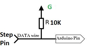
I was skimming, but I don’t think you really need a pulldown resistor, as long as your project would not have problems with a single step of the stepper motor during startup (typically, that means 1/200th of a rotation on the motor).

When I suggested very early in the setup (immediately) that you write
pinMode(pin,INPUT);
digitalWrite(pin,HIGH);

The reason for that is because the first step, pinmode input, sets the pins to “high impedance.” meaning they’re really just used for reading voltages in that step (they could not, for example, light an big LED). I said to make them inputs so that you could then write digitalWrite(pin,HIGH) that sets the internal pull-up resistors (automatically inside the arduino).

The pull-ups will work as easily the external pullups, because the drivers only step whenever they have a transition from low to high. So with this you’ll have a single almost imperceivable step, and then no chatter.

The problem is that ultimately you will need to declare

pinMode(pin,OUTPUT);

in order for your digitalWrite()s later on to actually step the motor. When it’s in input mode it’s not useful for powering to step signal on the Pololu drivers. That’s the drawback.

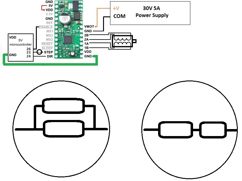
In this sense, I actually just realized it might make sense to ignore all this talk about pinMode(pin,INPUT). The ONE change you ought to make in your sketch is to move the part where you declare the pins to outputs to the top of void Setup(), and then after that also do digitalWrite(pin,LOW). This way they’ll be kept low until you start stepping. Do this for the pins that go to the step inputs on the driver. Don’t do it for all the pins, because I don’t know what other pins you have in your project. But if you example your pin was connected to a 5V battery, and you set it to LOW, then you would suck too much current into that pin (output mode does not have any resistors limiting the current in or out of the arduino. You have to make your circuit so that you don’t pull or sink too much current). But because the step pins on the Pololu driver have resistors, you’re fine in this example

FINAL POINT:

There must be something in your void Setup() that is taking a long time, for some reason. I’m unclear about this - I dont know what you wrote and haven’t carefully examined your response. The arduino bootloader typically does not take very long to go in the main loop (meaning, void setup and then void loop). It might just be the slightest moment of chatter, much much <1 second.

That diagram is correct. You have an Arduino pin connected to the driver step pin and additionally you have a 10k resistor between that pin and ground. That way, when the Arduino is reset and not doing anything with that pin, it has a constant value (0 V) and won’t make the driver take any steps.

- Ben