Recently, I’ve bought the Raspberry Pi dual G2 motor HAT to control 2 motors. However, when I assemble and solder everything and test run with example.py only motor 2 will work while motor have no response. I’ve checked the GPIO pin that controls direction of both motor and they both have signal coming through. Please find attached video to see only LED for motor 2 light up. Could anyone please advise?
From your description, I suspect there might be some solder joints that are not making a good connection. It is hard to see your soldering clearly in your video, but it does look like some of them (including some associated with M1) are likely not wetting properly. Could you try reworking the solder joints and trying again? Adafruit’s Guide To Excellent Soldering has some good references for how solder joints should look and how to repair common problems.
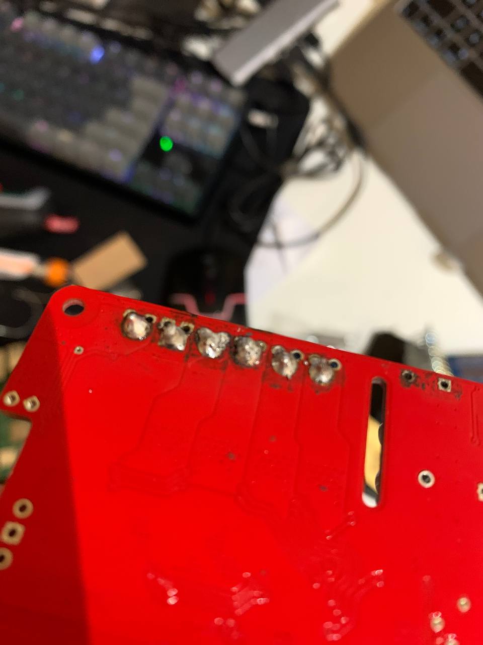
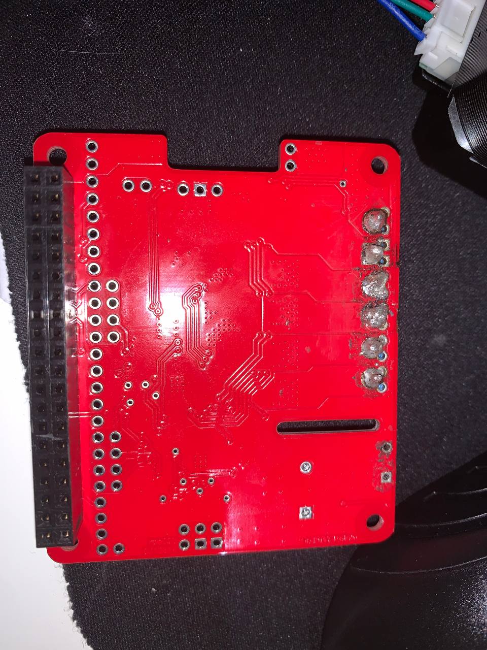
If you still have the problem after reworking the solder joints, could you post some clear, close-up pictures of both sides of your motor driver board?
Hi Brandon, I’ve applied tons more wetting to the pin and things do get better. However, there is a new issue coming up. When motor 1 run halfway to forward or reverse, it will stop midway and no more signal will be sent to the motor / LED of motor 1 won’t light up. Please find attached videos for reference, the first video shows the motor connect running for 1 sec and stopping halfway and won’t turn anymore. The second video shows it’s running in reverse but also stopping at mid way.
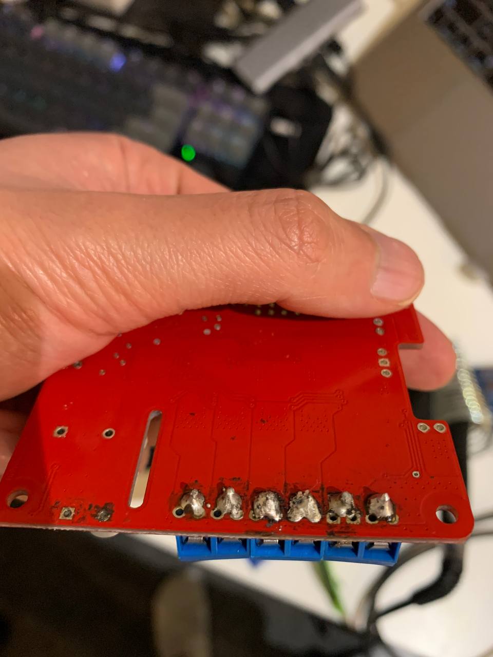
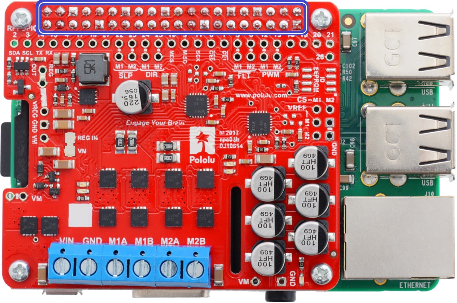
That is a strange behavior; however, it looks like you only reworked the soldering on the terminal blocks and not the 0.1" header pins, which still show some signs of improper wetting. Before troubleshooting any further, can you try reworking those pins, too? For reference, here is a picture with the pins I’m referring to circled in blue:
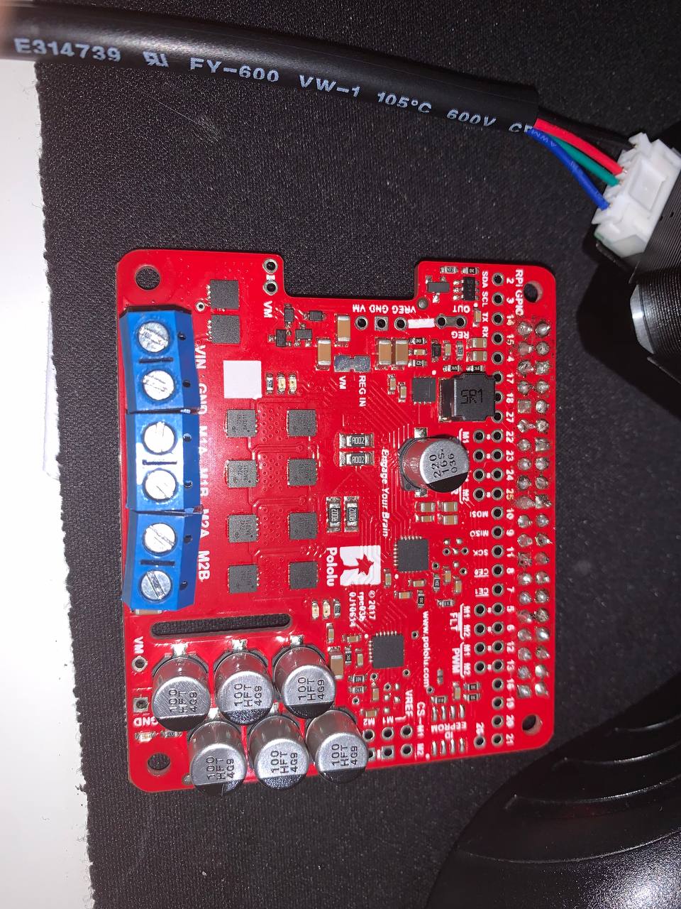
Thank you for your suggestions. I hate to say this but after resoldering the 0.1 pins, The issues are still the same. Attaching video and top and bottom of my HAT for reference:
If you switch the motor to M2, does the problem follow the motor?
I noticed in the previous video you posted without the motor connected, it looked like the motor red indicator LED for M1 was turning on before the green one. Are you running the unmodified example from our Python library for the Pololu Dual G2 High-Power Motor Drivers for Raspberry Pi or did you modify it in some way? If you are using that example, can you check to see if you are getting any driver fault messages?
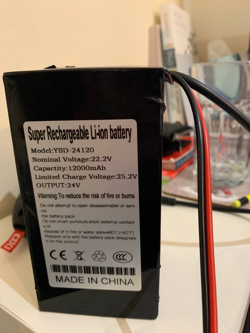
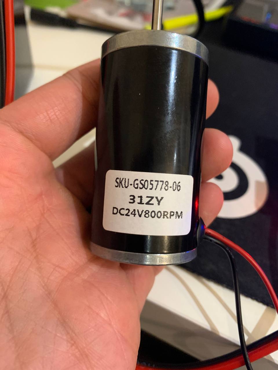
Also, could you tell me more about your power supply and motor?
The motors are working fine when connected to M2 in the clockwise and anti-clockwise directions. I did modify the program by comment out the clockwise test run to show that the direction of the motor spinning has no relation to the failure.
This is the video when connected to M1 using unmodified example.py https://streamable.com/jhi9nq
This is the video when connected to M2 using unmodified example.py https://streamable.com/tenocj
The problem will still exist with or without the motor connected
The battery I am using is a 24v 12000mAh Battery from eBay: https://www.ebay.co.uk/itm/185186274684
Thank you for the additional information. I do not know what would cause the output to suddenly cut off like that. Could you check to see if running the example program reports any driver fault messages? Could you measure the resistance between the M1 motor output pins (with the motor disconnected)?
Also, could you try measuring the input signals directly from the driver board at the pins indicated in the picture below with a yellow box to see if they are behaving as expected?
Thank you for your suggestion, Brandon.I have some good news! The board miraculously started to work a little after I let it sit for a few days. However, it still behaves strangely. I’ve measured the PWM signal from the driver board and here’s what I found:
When measuring the M1 PWM signal, I found out that the voltage of it won’t ramp up to 3.2v as the video below shown using the example.py https://streamable.com/h316be
While M2 PWM is ramping up steadily. https://streamable.com/apnqc2
PS: I still can’t post the link, sorry for the URL escape
I also tried a modified version to run both motors with MAX_SPEED at the same time for 5 secs with the following code in order to compare M1 and M2.
from __future__ import print_function
import time
from dual_g2_hpmd_rpi import motors, MAX_SPEED

# Define a custom exception to raise if a fault is detected.
class DriverFault(Exception):
    def __init__(self, driver_num):
        self.driver_num = driver_num

def raiseIfFault():
    if motors.motor1.getFault():
        raise DriverFault(1)
    if motors.motor2.getFault():
        raise DriverFault(2)
try:
    motors.setSpeeds(0, 0)

    motors.motor1.setSpeed(MAX_SPEED)
    motors.motor2.setSpeed(MAX_SPEED)
    raiseIfFault()
    time.sleep(5)
    motors.motor1.setSpeed(0);
    motors.motor2.setSpeed(0);
    time.sleep(1);

    # Disable the drivers for half a second.
    motors.disable()
    time.sleep(0.5)
    motors.enable()

except DriverFault as e:
    print("Driver %s fault!" % e.driver_num)

finally:
  # Stop the motors, even if there is an exception
  # or the user presses Ctrl+C to kill the process.
    motors.forceStop()
The results are like this:
M1 PWM started with a few hundred ms of 3.2V, and then drop to 2.5,2.6 for the rest of the test run https://streamable.com/44aaxx
M2 PWM giving out consistent 3.2v, very smooth https://streamable.com/5k0ywr
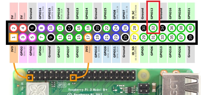
Those voltages you are measuring at the PWM pins are from your Raspberry Pi, so at 100% duty cycle (max speed) they should be measuring very close to 3.3V. Could you try removing the motor driver from the system and measuring the pin on your Raspberry Pi directly? The M1 PWM signal uses GPIO 12 on the Raspberry Pi (physical pin number 32); here is a diagram with that pin outlined with a red rectangle for reference:
If the signal coming directly from the Raspberry Pi pin is measuring 3.3V as expected, then I suspect there are still some connectivity problems in your soldering on that pin.
Thank you, Brandon! I followed your suggestion and measure the voltage directly at Pin 12. Looks like the signal from Raspberry Pi is not doing what we expected. I am using the example.py and the voltage from pin 12 dropped to 0 suddenly after rising to 1.1v. https://streamable.com/78hpbm
I am supplying the power directly with a Macbook charger so the power source should not be a problem. Do you have any idea what might be causing the problem?
That is strange; we tried testing our library again with a fresh install of the latest Raspberry Pi OS and couldn’t reproduce the problem.
Could you confirm that you are using a Raspberry Pi 4 Model B? (That is the board version I just tested with.)
If you measure GPIO13 instead (which controls M2), do you see the voltage ramp up to 3.3V and back down to 0 as expected?
Could you try to make sure your Raspberry Pi software is up to date? Could you run the commands cat /etc/os-release
and uname -a
and post their output here?
Have you installed any other software that might be accessing or reconfiguring the RPi’s GPIO pins and peripherals?
Do you have another Raspberry Pi you could try testing with?
Hi Kevin! First of all, Happy new year! I can confirm I am using a Raspberry Pi 4 Model B.
I measured pin 13 for motor 2’s PWM voltage and yes they will ramp up to at or around 3.3v and go back to 0, please find the following video for reference.
The following is the output of uname -a Linux raspberrypi 5.10.63-v7l+ #1488 SMP Thu Nov 18 16:15:28 GMT 2021 armv7l GNU/Linux
And because I am going to use the Pi with the DC Motors & Stepper Motor HAT from Adafruit, I followed the instruction from this page and done the following:
installed adafruit_blinka
enabled i2c
and the following is the output of pip3 list:
Your software versions seem fine to me. I still wasn’t able to reproduce the problem even after installing adafruit-circuitpython-motorkit (and it looks like their DC and Stepper Motor HAT uses I2C communication and doesn’t rely on the RPi’s PWM, so I wouldn’t expect it to mess with the PWM pins anyway).
So unfortunately, we still don’t really know what is causing the issue you are having. If you have access to an oscilloscope, that could help to get a better idea of what is going on with GPIO12. Trying another Raspberry Pi should indicate whether there is something wrong with the RPi board itself. If neither of those is an option, maybe you could try setting up a new SD card with just the minimum software necessary to run the dual G2 motor driver library example and see if the problem still occurs.
You could also try this minimal test program to see what happens:
import time
import pigpio

_pi = pigpio.pi()
if not _pi.connected:
    raise IOError("Can't connect to pigpio")

for p in [12, 13]:
    print(f"Testing pin {p}:")
    for d in [0, 30, 60, 90, 100, 0]:
        print(f"{d}% duty cycle")
        _pi.hardware_PWM(p, 20000, d * 10000)
        time.sleep(2)
    print()
It should drive pin 12 and then pin 13 at 0%, 30%, 60%, 90%, and 100% duty cycles for 2 seconds each, which should produce average voltages of about 0V, 1V, 2V, 3V, and 3.3V. I don’t expect this test to behave much differently than the library example program, but you might still try running it and measuring the PWM pins with your multimeter to see if that can tell us anything. (I suggest leaving the motor driver disconnected for now unless we can verify that the RPi works fine without it.)
Thank you for putting your time into the investigation. I’ve run a fresh install of the Raspberry pi OS but pin 12 is still not providing the correct output. I think the pin/the board might be broken or something. I then have the idea of remapping GPIO 12 into another pin that supports hardware PWM. I tried GPIO 18 but it’s not working then I tried GPIO 19 and it worked. Would you suggest I remap the M1 PWM signal from GPIO 12 to GPIO 19? Any concern behind that? Thank you very much!
Remapping the PWM output is a good idea. However, I’m reading that GPIO12 and GPIO18 share one PWM controller channel (PWM0) while GPIO13 and GPIO19 share another (PWM1). If that is the case, then I don’t think you will be able to have independent control of PWM on GPIO13 and GPIO19 at the same time; have you tried to do that?
The fact that you can’t get PWM to work properly on GPIO18 also suggests that the PWM0 channel is either misconfigured or damaged.
That’s a bummer. I would need both motors to work independently. I would try to resolve the PWM0 channel issue or try to get a replacement from the retailer. Thank you!