Hello Brandon,
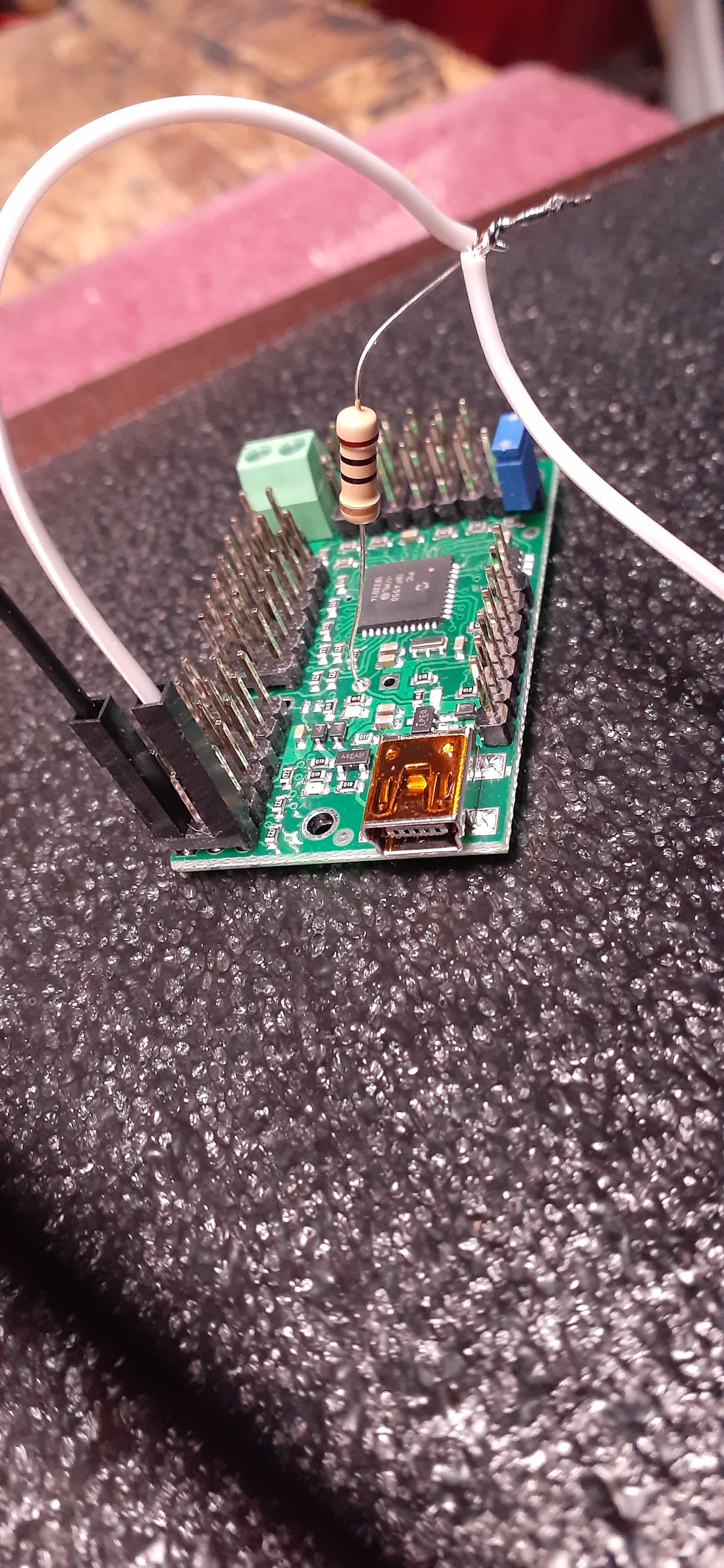
OK I’m using a 10 ohm resistor that you may have suggested in an earlier post.
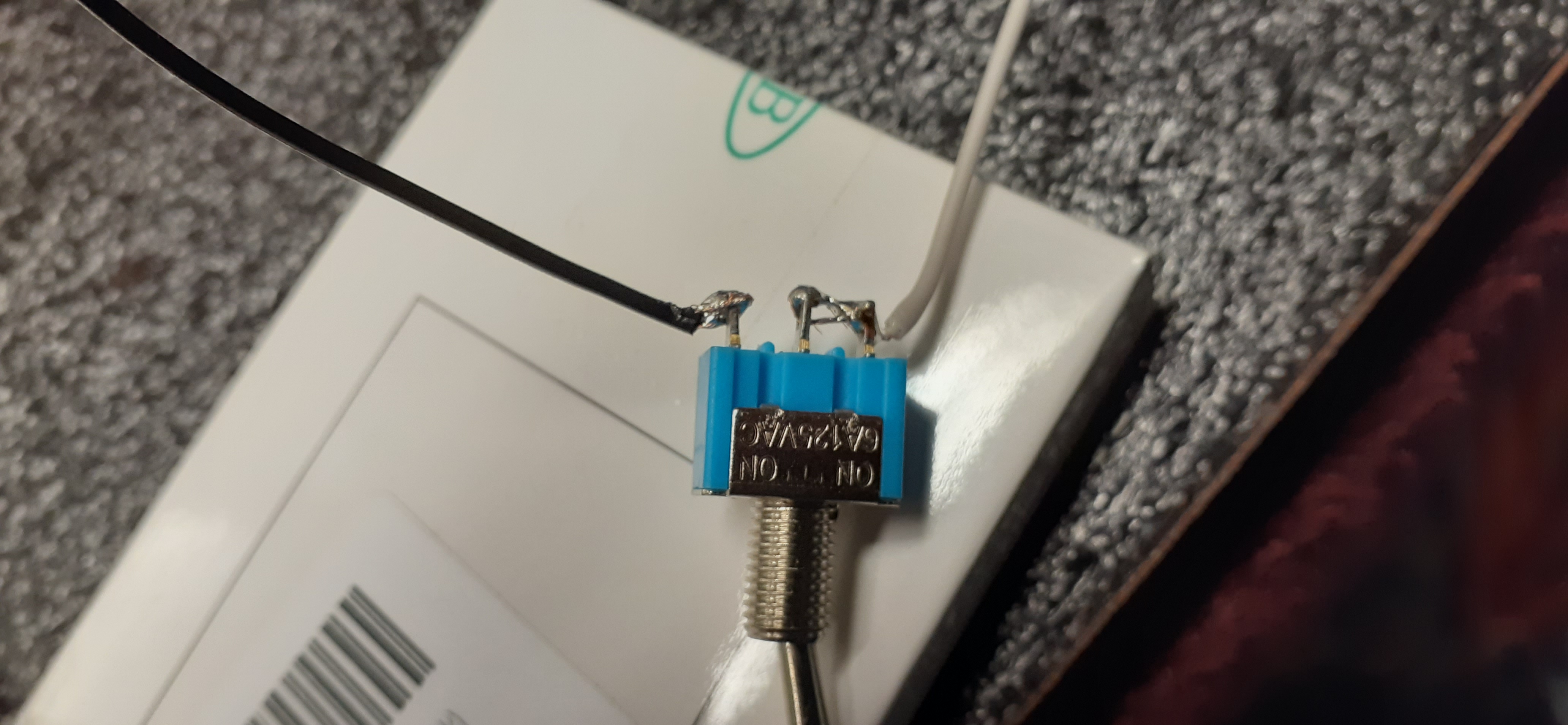
In the switch picture the white wire is connected to the middle position only
and in between Is where the resistor is
it is soldered to the maestro to the 5v slot on the maestro
then white wire plugged into (I think is called) the Control position
The black wire is then connected to the maestro in the ground position
Keep in mind the program is showing a solid 3 on the low end and a solid 255 on the high end
with no jumping
It’s just the resistor is getting hot and I don’t know why? Confusing…
Maybe I need to use the 1 – 100 ohm resistor?
Thank you for the pictures. It sounds like you misread the resistor that I recommended earlier. That resistor should be between 1kΩ (1000Ω) and 100kΩ (100000Ω). Using the larger resistor (something like 10kΩ) will reduce the current through the resistor by several orders of magnitude, so that should fix the heating up problem; it looks like you have the connections made in the right locations.
Brandon
Sorry you’re probably right I have no idea what I’m reading when you told me the size of the resistor like I told you from the beginning when it comes to these many electronics I am a mega novice so I will try a larger resistor and hopefully that will solve our problem and then I will try the code that you sent and we’ll go from there thanks again for getting back to me.
John DiGiacomo
1 Like
Brandon
Hope this finds you well?
OK so here we are
May 2 Great News “It Works”
and its not getting hot using a 10k ohm resistor.
I have been fooling around with the settings and
Slowing it down
Thank You for all your Help
and most of all being Patient
Now the task of getting 9 switches and 9 servos to work independently
I think I know what to do
Need to organize my project and get started
any and all wire organization suggestions always welcome
Think I’m going to use a bread board no sure have to keep it labeled and organized
Thanks Again
John
1 Like
Hello Brandon
I’m assuming that the reason the servo I have only moves in a limited motion is because it’s not a 360 servo??
Are thay all different and fo that all have specific movements and restrictions?
Thanks John
Every servo has it’s own range of motion specifications; generally speaking, you can usually get about 90 degrees of movement over the standard 1ms to 2ms pulse width range, but that pulse width range could correspond to 100 degrees on one servo and 80 degrees on another servo. you can extend the pulse width range you are using to try to get some extra range of motion, but this should be done cautiously as commanding a servo beyond its limits could cause it to damage itself. You can find one method we suggest for finding the maximum range of your servo in the “FAQs” tab of the Maestro product pages.
In my experience, it is fairly uncommon to get much more than 180-degrees from a standard servo. If you need more than that, you might consider getting special full-turn or multi-turn servos (sometimes called “sail winch” servos). Note that these are different from continuous rotation servos, which sacrifice position control for endless rotation.
Brandon
Hello Brandon
So If i wire each servo and switch independently
A. will each switch need it’s own resistor?
B. will each switch and servo work on it’s own independently?
Thanks John
 John DiGiacomo
Hello, John.
Each switch will need it’s own resistor to work independently from the others.
How the switches and servos interact is up to your script. The script I walked through in my earlier post only reads one switch (on channel 0) and controllers 1 servo (on channel 1). In order to have additional switches control additional servos, you would need to expand on that example.
Brandon
Okay great Brandon
When I experimented with it I moved the switch to a different position and a Servo to a different position and then change the script and it worked well I just thought maybe I could put one resistor and Bank all the switches together but wasn’t sure I appreciate the feedback thanks again John
John DiGiacomo
Hello Brandon
So next I would like maybe to add a small LED bulb to show which position the switch was in
Where might I add that?
I’m guessing in line with the switch lead?
Thanks John
You could probably put it in-line (series) with the switch or in parallel with the switch (which would light at the opposite switch positions); however, in either case it would be in series with the 10kΩ pull-up resistor, so it might be pretty dim.
Brandon
Hello Brandon
Lost your email would like get again to send u some updates pics of what I’ve done so far with the switches and servos
Anyway I need to know how I could couple another maestro using the same power cord
Do I take it from the jumper lead??
Thanks John
It sounds like you asking about powering two Maestros from the same power source. You should be able to run another set of power wires in parallel from your power source to your second Maestro (without going through the first one). Powering the second Maestro in series with first one is not a great solution, since the header pins (like the ones with the VSRV=VIN jumper) are only rated for upwards of 3A.
Brandon
Hey Brandon,
Hope all on the forum and at pololu are staying safe and smart.
So it’s been a few weeks now and things are progressing the second maestro has been prepped and ready to go at my home layout.
At my train club we have been installing servos and our first Maestro in some new applications and going to test there reliability, I’m sure thay will be fine.
Just wanted to give u an update and wish you a healthy and happy summer. Hopefully all this will pass soon.
Were you able to see the pics I sent did you post them somewhere if so I missed them.
Thanks for all your help. Will keep in touch now and then.
John
1 Like
Good morning, John.
Yes, I got the pictures; thank you for the detailed email. It’s really neat you are expanding the Maestro use to your train club! We’d love to hear about their experience with it; especially if they have any more feedback.
Brandon
Good Morning Brandon
So we have come along way and things are progressing well
I was able to adapt the Pololu servo configuration to work two Train Crossing gates on the Train Clubs layout using embedded infrared sensors for switches works well very happy! 
So now I’m ready to add switch lights to my layout
I’m looking for Pololu product rival to the Arduino Uno I think
I want set up two LED lights on the same signal to be green for go when track is open and red for stop when track is closed almost like a traffic light without the yellow unless that’s available as well dont know
possibly adding sensors in the track later as switches for automatic functions
Any Ideas
Thanks John 

So Brandon
How have you been? Hope you all are well.
Making great progress with the maestro at the train club we have added several to our projects will send you some pics when were done with the latest gate project. We will be controlling 8 crossing gates 2 manuel switch and 6 automatic with a sensor
So my question is it possible to connect or run my 2. . . 12 position maestros so 1 holds the switches and the other holds the servos??
In other words instead of having 2 maestros with 6 switches and 6 servos I could maybe manage better if on has switches and one has servos
Thanks John
I have been doing well, thanks.
It’s great to hear your train club is still having success and enjoying the Maestros!
There are a couple ways to do what you described, but probably the easiest (and closest to what your script is already doing) would be to have the “switch” Maestro do all the processing and send Set Target commands through the TTL Serial interface to control the servo channels on the other Maestro directly.
It looks complicated, but all you would really need to do is put the subroutine copied below in your script, then change all of your “servo” commands to be “set_target” instead:
sub set_target

  #First byte 0x84: set target command byte
  132 serial_send_byte

  #Second byte: servo channel
  serial_send_byte

  #Third byte: lower 7 bits of target
  dup 127 bitwise_and serial_send_byte

  #Fourth byte: bits 7-13 of target
  7 shift_right 127 bitwise_and serial_send_byte

return
Then all you would need to do is configure the serial settings and connect the TX pin from the “switch” Maestro to the RX pin on the “servo” Maestro, along with a common ground connection. For the code above to work as-is, both Maestros should have their serial mode set to “UART, fixed baud rate” in the “Serial Settings” tab of the Maestro Control Center, with the same baud rate set on each (9600 is the default and probably good for most applications).
You might also consider upgrading to the 24-channel version of the Maestro to keep it all on one device.
Brandon
Thanks Brandon
That was the other solution
and i think the best the train club nees a 12 channel i will donate one of mine and upgrad to the 24 channel for my self
will stay in touch and forward picks to you as soon as the project is finished
including possible video and i know you like details
John
1 Like