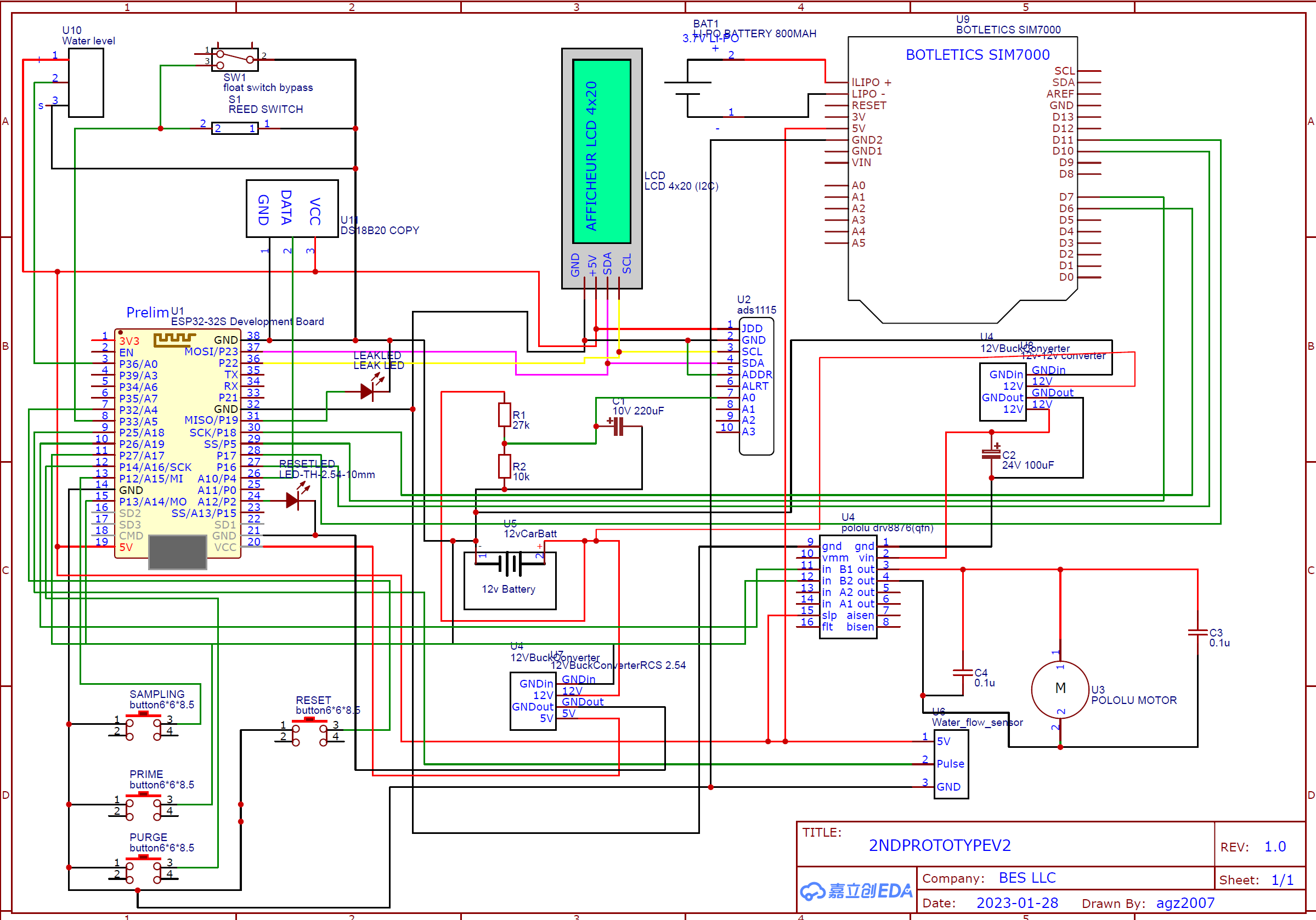
I am developing a portable water sampler using the DRV8874 to driver the dc motor attached to a peristaltic pump head. I’m also using an ADS1115 ADC to measure the battery charge as a percentage as the sampler is intended to run off a 12V LiFEPo4 5AH battery and sends text messages to warn when battery percent is below 20%. when the DC motor runs, battery charge drops from 100 to 2 percent, so I added a bunch of capacitors which made it drop less to about 70-75% whenever motor is running. I was wondering if I could recieve guidance on how to eliminate the voltage drop from the circuit. the schematic im attaching doesnt include all the capacitors i’ve installed today for troubleshooting, but basically I have 5 100uF 25V capacitors wired in parallel going to the VIN and GND pins of the DRV8874, and 6 100uF 16V capacitors wired in parallel going to the converter/regulators which provides power to the driver
edit: Motor draws .5 amps and is powered by 12vdc
edit: the behavior is the same whether I use a 5AH or 10AH battery and also when using a regulated power supply
I can see there are many other components in your circuit including a SIM7000 module. Have you tested your DRV8876 and motor separately with a power supply? Disconnecting them from the SIM7000, LCD etc.?
Yes, the problem was identified early in development. first I developed the ADC circuit and code and tested it, which worked, then I connected the circuit to the motor driver and motor, which is when I started to notice the massive voltage drop. All other components were added after the identification of the bug since I didn’t have enough time left to troubleshoot the issue at the time as it was overdue for field testing. I was only able to minimize the issue by adding the capacitors in the schematic, but it never resolved it. my only other idea is use to code the ADC to not run when the driver logic pins are energized
Where are you measuring the battery voltage? How long are the wires between your battery, regulator, and motor driver? Please post pictures of your setup that shows all connections.
By the way, one of the regulators in your schematic is labeled “12V buck converter”, but is supplied by a 12V battery. If the regulator is just a buck (rather than buck/boost), the output voltage of the regulator could be dropping as the battery voltage approaches and goes under 12V.