I bought the mini maestro servo controller and shiftbite led with the 6x1 pin header cable. This was to allow me to easily connect them together. I cannot find info showing where to connect the other side of the cable at on the controller board. Or is it the fact I have to make a cable to hit the pwr pin, the gnd pin, and three signal pins to control the led? what other pin needs to be connected to control a chain of shift brite leds?
You bought a Micro Maestro. There is no “Mini”, yet… Anyway, there is a picture of the wiring I used on the Shiftbrite page, along with a description, which I think should make it pretty clear. The “other pin” you are thinking about is probably the enable line, which I have wired to ground to leave the controller permanently enabled.
When you talk about “the pwr pin”, please make sure you are thinking carefully about where the power is actually going and what voltage each part will be getting. The Maestro has a bunch of different pins that could be casually called “power”.
-Paul
Yes, I was wrong, a micro maestro.
So, the custom cables I bought only connect the two shift brites together they DO NOT connect the shiftbrite to the maestro, correct?
Is it reasonable then to take one cable cut it in half, take the red and black wires put them in a two pin connector on the VIN and GND pins of the serial com pins. and the Yellow and green wires to a 3 pin connector placed on servo 0 slot on signal and -.then the white and blue wire to another 3 pin connector to go across servo1 signal pin and servo2 signal pin.
Yes, the cable is just designed for connecting two shiftbrites to each other. If you have any of our crimp connector housings, you could use a small screwdriver to remove the connectors from one end and plug them in to new housings. Otherwise, yes, it sounds totally reasonable to cut the cable, and your connections are almost fine, but you need to explain where power is going to be connected.
-Paul
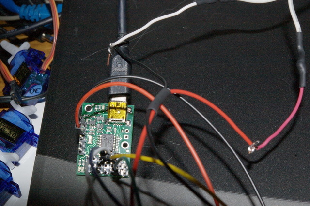
Ahhhh, you are right I see the red and black wires going out of frame, that is to a 5V wall wart???
For now I could power it just from the USB plug?
If I can just use USB power now, where would black and red connect to power the shift brite???
Hello,
The circuit in the picture is powered by a 6V regulated supply. I do not expect it to work very well at 5V, since that is below the minimum operating voltage of the Shiftbrite. And the USB port might actually supply significantly lower than 5V.
-Paul
Okay then, 6V I have a 3-12 1A source from R/S. so do the red and black wires branch off to the power source thus powering the board and the shiftbrite. That picture is not very clear about the source of power.
Then the USB just sends the script?
Why is the green wire also going to – on the servo pins
You can program a script onto the Maestro via USB. After that, it runs autonomously.
Are you asking why or what? I thought you understood that one. The green wire is the enable line, and it goes to ground so that the ShiftBrite will be permanently enabled.
-Paul
I believe I have all the wires correct, however I wonder if the board power gets power to the servo pins? since I am powering the board with the usb for now (when I am done experimenting I will apply a battery) I applied the power to the servo + and -.
I keep getting a stack overflow/underflow error code 0x0040
I read the manual 3 times trying to understand this error, I stepped thru the script, I analyzed the script line by line to see a typo. Channel settings are pins 0,1,2 as output. serial setting is UART fixed baud rate 9600. I dont get it.
Is there a way to test my shiftbrites using the drag bars on the status tab?
Why would you need power on the servo pins? You do not have anything connected to the servo power, right?
If your script is giving a stack error, the sequence of commands it is running is just wrong somehow. For example, do something 10 times in a loop like this:
10
begin
  dup positive # check if the loop variable is positive
while
  1 minus
  # ... your loop code here ...
repeat
you need to remember to drop the final value of zero after the loop is complete, or that zero will stay on the stack, and every time you execute the loop, the stack will get one level deeper, until there is an overflow. That is my most common mistake, anyway!
Try using the Maestro Control Center to step through your code, and make sure that every line does exactly what you expect. Most likely you will catch the problem after stepping through your main loop once or twice. If that is too hard, you could insert large delays at key locations and just watch the code while it runs. Of course, you can also post your code here and have us take a look at it!
You could do it with the drag bars, but it would be a huge pain - you would have to toggle the clock line line by hand dozens of times to get a complete packet transmitted, and by then I bet you would lose count and end up sending the wrong bits on the data line.
-Paul
Its the example code with th manual.
I stepped thru the sub routines until I saw it going in circles, it seemed to just be swapping values to load in the 10 bit value then sends that value. It appears to change up on which pin data is going to.
# Subroutine for setting the RGB value of a ShiftBrite/ShiftBar.
# example usage: 1023 511 255 rgb
sub rgb
	0 send_bit # this bit does not matter
	0 send_bit # the "address" bit - 0 means a color command
swap rot rot
send_10_bit_value
send_10_bit_value
send_10_bit_value
0 1 8000 1 servo servo # toggle the latch pin
return

# sends a numerical value as a sequence of 10 bits
sub send_10_bit_value
512
begin
dup
while
over over bitwise_and send_bit
1 shift_right
repeat
drop drop
return

# sends a single bit
sub send_bit
if 8000 else 0 endif
2 servo # set DATA to 0 or 1
0 0 8000 0 servo servo # toggle CLOCK
return
Please use the “Code” button when entering code on the forum - it is much easier to read that way.
Anyway, that example code just defines some subroutines. You have to actually use them to do anything. At the beginning of your code, try adding
1023 511 255 rgb quitThis should send a single color command to your ShiftBrite. Note in particular the quit. Without that, execution would continue into the first subroutine, and when the return is reached, and you immediately get a call stack overflow/underflow error.
-Paul
Oh boy. I am trying real hard to understand this code. I read the pdf that came with the maestro. Is this code the same as Arduino? it seem similiar but Id int know. I know someone with a arduino. I have been messing with picaxe for the last year, this seem different.
Can you tell me how to turn on the shift brite with a color for now, then I can change the code for the color and play with it.
I can figure out the delays to make it blink, but what makes it dim?
The code has nothing in common with Arduino. The language on the Maestro is a very simple, stack-based language, basically the simplest language we could think of so that we could give the Maestro come kind of scripting ability. It is not easy to figure out a ShiftBrite control program in any language, and it is definitely at the limits of what I expect anyone to be able to do with the Maestro, so I am not too surprised that you are having trouble understanding the subroutines. However, I did give you very explicit instructions in my previous post about how to make the ShiftBrite turn on using the subroutines - did you try adding that line to the top of your code yet?
I really do not know what you mean by this question. If you are asking how to send a dim color, the answer is that you just use low values for the R, G, and B numbers. If you are asking how the ShiftBrite works, do a Google search for “PWM”.
-Paul
Yes I did try. I put it at the top, after the two comments. Then I tried the idea that that this was an explicit command, so I cleared everything and had that as the only line. I did not get the overstack error but the led did not come on in either try. I did notice the little red triangle stopped at the quit command and dimmed. The buttons to run the script came back and though I pressed again it did not do anything.
Hello,
It is going to be hard to help you if you do not explain what is going on more clearly. For example, you did not tell me about any difference between when you deleted most of your code (which should have caused an error because of the undefined subroutine) or when you tried it the way I suggested. Did you actually apply the code the second time? Did you make sure to reset everything before trying? Can you post your entire code and a picture of your wiring?
-Paul
<!--Pololu Maestro servo controller settings file, https://www.pololu.com/catalog/product/1350-->
<UscSettings version="1">
  <NeverSuspend>true</NeverSuspend>
  <SerialMode>UART_FIXED_BAUD_RATE</SerialMode>
  <FixedBaudRate>9600</FixedBaudRate>
  <SerialTimeout>0</SerialTimeout>
  <EnableCrc>false</EnableCrc>
  <SerialDeviceNumber>12</SerialDeviceNumber>
  <SerialMiniSscOffset>0</SerialMiniSscOffset>
  <Channels ServosAvailable="6" ServoPeriod="156">
    <!--Period = 19.968 ms-->
    <!--Channel 0-->
    <Channel name="" mode="Output" min="3968" max="8000" homemode="Ignore" home="3968" speed="0" acceleration="0" neutral="6000" range="1905" />
    <!--Channel 1-->
    <Channel name="" mode="Output" min="3968" max="8000" homemode="Ignore" home="3968" speed="0" acceleration="0" neutral="6000" range="1905" />
    <!--Channel 2-->
    <Channel name="" mode="Output" min="3968" max="8000" homemode="Ignore" home="3968" speed="0" acceleration="0" neutral="6000" range="1905" />
    <!--Channel 3-->
    <Channel name="" mode="Servo" min="3968" max="8000" homemode="Off" home="3968" speed="0" acceleration="0" neutral="6000" range="1905" />
    <!--Channel 4-->
    <Channel name="" mode="Servo" min="3968" max="8000" homemode="Off" home="3968" speed="0" acceleration="0" neutral="6000" range="1905" />
    <!--Channel 5-->
    <Channel name="" mode="Servo" min="3968" max="8000" homemode="Off" home="3968" speed="0" acceleration="0" neutral="6000" range="1905" />
  </Channels>
  <Sequences />
  <Script ScriptDone="true"># Subroutine for setting the RGB value of a ShiftBrite/ShiftBar.
# example usage: 1023 511 255 rgb
1023 511 255 rgb quit
sub rgb
	0 send_bit # this bit does not matter
	0 send_bit # the "address" bit - 0 means a color command
swap rot rot
send_10_bit_value
send_10_bit_value
send_10_bit_value
0 1 8000 1 servo servo # toggle the latch pin
return

# sends a numerical value as a sequence of 10 bits
sub send_10_bit_value
512
begin
dup
while
over over bitwise_and send_bit
1 shift_right
repeat
drop drop
return

# sends a single bit
sub send_bit
if 8000 else 0 endif
2 servo # set DATA to 0 or 1
0 0 8000 0 servo servo # toggle CLOCK
return
</Script>
</UscSettings>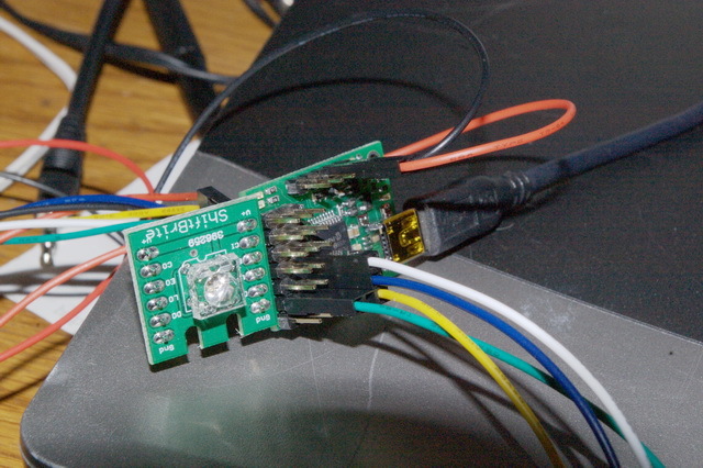
Your settings show that the script will not run on startup. How did you attempt to run it? Can you describe every step that you did, starting with everything unplugged? I can’t see your power connections in the picture, but everything else looks okay. Can you post a picture of that part of the wiring?
-Paul
Okay. I connect the header with 6v and gnd to the maestro board power. red to VIN blk to GND. The green wire in a three pin header goes to servo 0 GND the Yellow to servo 0 signal. Blue wire in a two pin header goes to servo 1 signal, white goes to servo 2 signal. I first insert the mini usb plug into the board. Then I plub the usb into my laptop. I start the software. The script is already loaded. I check the settings so servo 0,1,2 are outputs. then I check the serial settings to see it is UART fixed baud rate 9600 then I enable all three ports. go to the sxript tab and push run script.