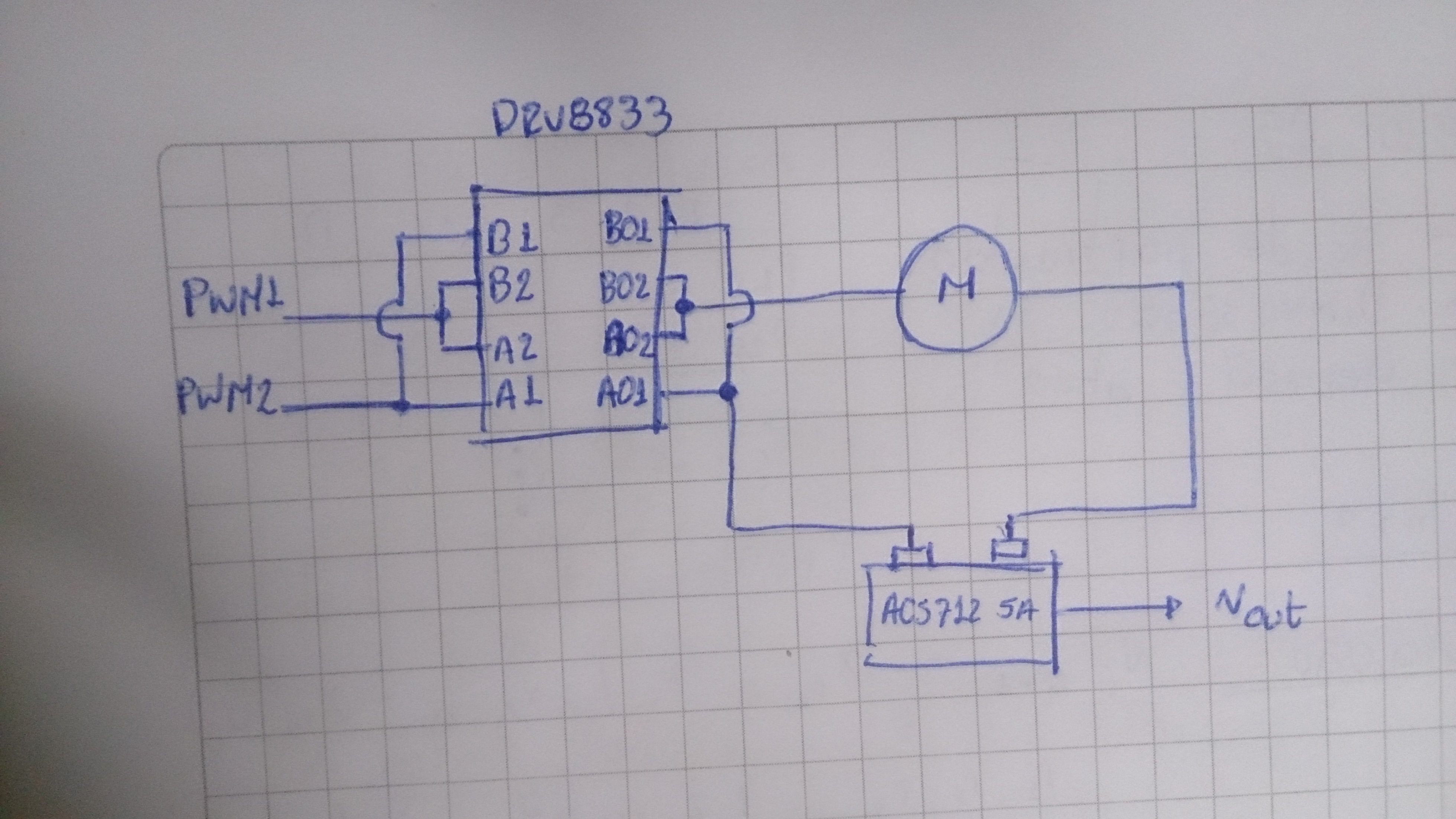
Here is what I want to do, I want to control the current on a Pololu micro motor. Im using the DRV8833 driver and the acs712 5a current sensor, the schematic is something like this:
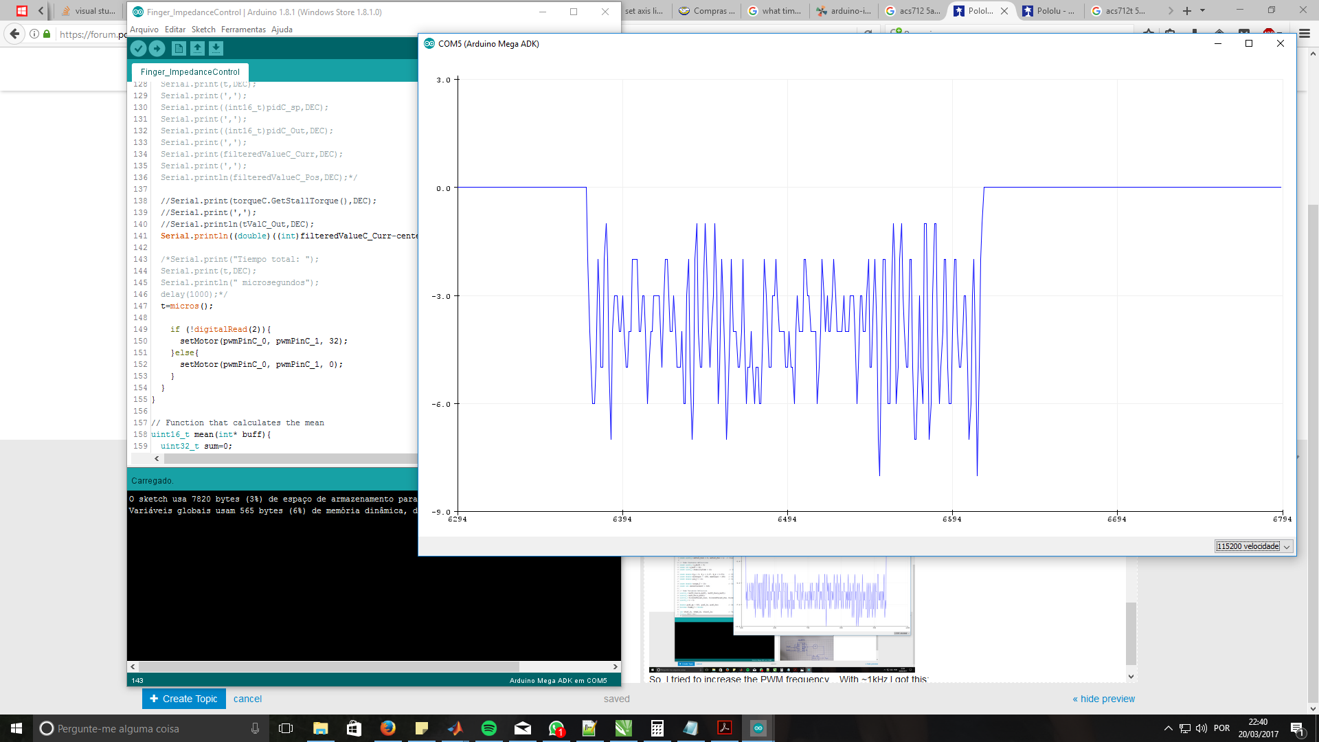
So virtualy It had less error but it was measuring less currten with the same duty cycle than all of the previous experiments. And didnt even got to move the motor…
Can any of you help me figure out my problem…
PD: I checked the frequencies with an oscilloscope and they were OK
PD2: The scale in the graphics is [512, -512]
PD3: If there is another information that you require please tell me
In general, it is not unusual to some variation in motor performance at different frequencies. What duty cycle are you running your PWM at and what is the current at 100% duty cycle? What states are you cycling the H-Bridge between (Drive/Coast or Drive/Brake)? Have you looked at the output of the current sensor with the oscilloscope to try to see if the current consumption varies with the PWM state?
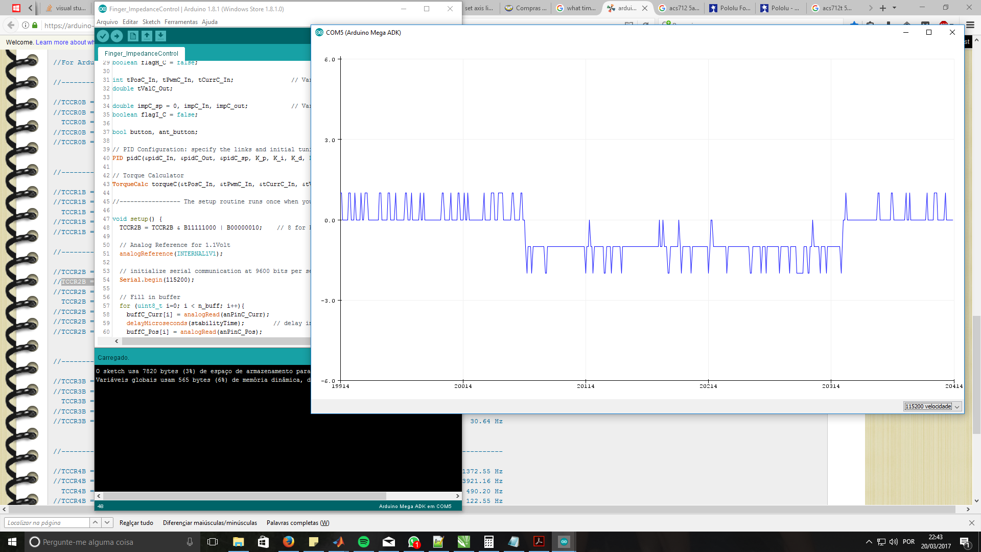
The duty cycle was 12%(12% out of 8vots ~ 1volts). What I wanted was to stall the motor with a small current to compare the measurment of the sensor with a multimeter. At the lowest PWM frequency (~500Hz) this current was almost 9mA (in the multimeter), but with a frequency of ~4kHz this value only got to 1mA, finally, at 30kHz the multimeter grabbed nothing.
Before I do the experiment with the oscilloscope and the current (I’m not at the lab anymore), I wanted to understand more about this question
Do you happen to have a link with information about this?? But if clarifies anything, for the experiment I didn’t change the current’s polarity in the H-Bridge.
It seems like you quoted the wrong question in the second part of your post. Are you asking about states of the H-bridge? You can find information in section 8.3.2 (beginning on page 9) of the DRV8833 datasheet about different drive cycles.
Yeah… I quoted the wrong question, I changed it already. I did asked about the states of the H-Bridge… after reading the information you gave I’m pretty sure that I’m using the driver in drive/coast with fast decay… do you thing using it in slow decay could solve my problem??
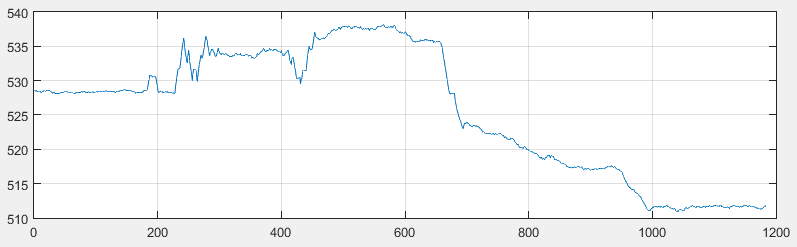
So… I switched the driver and used it on slow decay mode and guess what??? It solved my problem!!! I’m now using the driver and motor at 30kHz and works just perfect, also the noise in the current sensor got reduced a huge ammount; of course, this was also because I added a simple moving average filter, but still, the error got even more reduced using slow decay!!! See pics: