Micro Dual Serial Motor Controller

Hey guyz, i am VVVVVVVVERY confused about how this motor controller works :frowning: and need some assistance getting it running… I have read and re-read the book about 10 times to try and make sense of if but it is very confusing to me and i need to know how the microcontroller works so i may program my microcontroller correctly to send out the correct serial signal.

first off, i want to make this as simple as possible and all i need is for the robot to move forward!

I have 2 motors, but I want to make the them both move at the exactly same time forward.

Can anyone help me understand how this Motor controller operates so i may continue programming my microcontroller. Thank You

I have a few quick questions for you first, just to get us on the same page:

What kind of microcontroller are you using to command your micro dual serial servo controller (lets call it the uDSMC for short)?

What is your power source for the motors (1.8V-9V)?

What is your power source for the uDSMC logic supply (2.5V-5.5V)?

What connections have you made between the uDSMC and your micro controller? Between the uDSMC and your power sources?

And just for good measure, lets cover the basics. You’ll want to connect up your motor controller like in the manual:

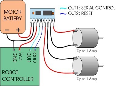
Pin 1 is the motor power supply, and Pin 2 is the common ground. The motor power source doesn’t necessarily have to be the same as your microcontroller’s power source, but both grounds do need to be connected.

Pin 3 is the logic supply pin for power to run the electronics on the uDSMC. It should most definitely be separate from the motor power, and be between 2.5V and 5.5V. You can probably steel power from your microcontroller’s battery or regulated supply.

Pin 4 is the serial input pin, which should be connected to the serial TX line of your microcontroller. You want to send TTL-level, non-inverted 8N1 (8-bit, no parity, one stop bit) serial bytes to the uDSMC. We’ll get into the command protocol in a second. The uDSMC will automatically detect your serial baud rate (from 1200 to 19200 bps) when you send the first byte. It expects to keep receiving bytes at this baud rate, so if you want to change your baud rate you have to reset the uDSMC first.

Pin 5 is the reset pin, which is maybe a little counter-intuitive. For your motor controller to function at all, this pin has to be pulled up to the logic supply voltage. As shown in the wiring diagram above, you can connect it to a digital output pin on your microcontroller and bring that pin high to start up the uDSMC (and low to reset it if/when you want to). You can also permanently pull the reset pin high by connecting it through a resistor (around 4.7 Kohm) to your logic supply voltage.

Finally, pins 6 and 7 go to one motor, and pins 8 and 9 go to the other.

Then you have to figure out what bytes to send according to the Pololu serial control protocol. It helps to understand binary, decimal and hex bases, but it’s not critical.

Basically every command must start with the special start byte: the number 128 (which is 0x80 in hex, or 0b10000000 in binary). In binary, 128 has 1 high bit, followed by 7 low bits, and it is the only number with 1 as it’s high bit allowed by the protocol (it’s special, so the uDSMC can recognize it as the start of a new command). So, all other numbers in the protocol will be between zero and 127.

The number after the start byte is the device ID, which is 0 for Pololu motor controllers. The section that has to do with configuring the motor controller using device ID 2 comes first in the manual, but that’s more complicated and you only need to do that if you want to use multiple motor controllers on the same serial line, or to switch your controller into single motor mode. You don’t want to do either of these, so let’s just use the default configuration, which means the device ID byte should be 0.

The next number is the motor number and direction together. As I mentioned above, the motor numbers are programmable so that you can have many controllers on the same serial line, but all controllers will respond to the motor numbers 0 and 1, so lets use those. The formula for this byte is (motor number)*2 for reverse, and (motor number)*2+1 for forward. So the byte values you want to consider are:

Motor 0 reverse: 0
Motor 0 forward: 1
Motor 1 reverse: 2
Motor 1 forward: 3

Finally, the last byte is a speed command, from 0 to 127. As you would expect, 0 means stop, while 127 means full speed in the direction you specified in the last byte. For speeds in between, try numbers in between.

So, to sum up, in each command you want to send:
128 - Start Byte
0 - Device ID
0, 1, 2, or 3 - motor number and direction
0-127 - motor speed

If you send two commands one right after the other the motors will start up at almost exactly the same time, and you won’t even be able to tell the difference.

So, what still doesn’t make sense?

-Adam

first off Adam, i would like to thank you for your help. You helped clarify one of the most confusing parts for me, and that was the “configuring the motor controller” and “using the motor controller”.

at first i thought that you must send the 3byte serial command to initalize the uDSMC and then send the 4byte serial data to “USE” the motor controller. Which threw me off because both start with the Start Byte of 0X80 which is the magic byte to let the uDSMC know that a knew byte or data is starting.

im gona answer all ur questions u sent me first:
What kind of microcontroller are you using to command your micro dual serial servo controller (lets call it the uDSMC for short)?
I am using the Atmega16 with a frequency of 3.6864Mhz which gives a 0.0% error rate for serial which is good with a baud of 9600, 8 bits, no parity, and 1 stop

What kind of microcontroller are you using to command your micro dual serial servo controller (lets call it the uDSMC for short)?
I will be using 7 Volts with im hoping 1Amp of power to the motors which are rated for 7.2VDC

What is your power source for the uDSMC logic supply (2.5V-5.5V)?
Im hoping to regulate 5VDC with a regulator from the Batteries that are giving off 7VDC but since you said it should be a different source and im pretty sure the motors are gona be causing alot of interference and noise on that line. and yes the grounds will be a common ground

What connections have you made between the uDSMC and your micro controller? Between the uDSMC and your power sources?
i have not made any connections yet as i have not made a powersupply yet to power all this. I am still trying to understand it so i know what to program the microcontroller. I have 3 small power supplies i made and will use those for testing purposes for now

Adam, i do understand the binary system and all that so you throw all those terms at me as i am used to them.

this is what i have gotten so far to send serial to the uDSMC:
Byte 1 = (10000000) or (0x80)
Byte 2 = (00000000) or (0x00)
now here is my lost part because of the type of motors i have. I have a motor that has a 2 power connections, and 2 grounds! this is what the manufacture sent me about the motors and you will have to excuse me because i have HARDLY ever used motors before
• Red Power Wire: Vcc Power In (0 - 7.2 volts)
• Black Power Wire: Gnd Power In
• Encoder Connector Red Wire: +5V
• Encoder Connector Black Wire: Gnd
• Encoder Connector White Wire: Channel A
• Encoder Connector Green Wire: Channel B
the 4 encoder wires throw me off according to how the motor is supposed to be attached to the uDSMC. especally with your diagram with the 2 motors and the power and ground wire going to pins 6-9. I emailed the manufacture to help clarify what channel A and B are?

Byte 3 is now my confusing part:
so since i have 2 motors, i need to send 2 4-byte serial data to them. What does it mean in the manual by motor # ? i know i have 2 motors, but is one 0 and the other 1? The manual says something that consues me somehow, and it says " Bits1-6 specify motor number. All motor controllers respond to the motor(s) 0 (and 1, in dual-motor mode) " so according to the formula, since i want both moving forward i go:
motor 0 = (0 * 2) + 1 = 1
motor 1 = (1 * 2) + 1 = 3
is this correct?

Byte 4 i understand and can choose any speed i desire…

I again thank you and appreciate allllllllllll your help :slight_smile:

Yeah, I’ve used a few of these little guys, and I seldom feel the need to go into configuration mode. The default setup works just fine if you’re only using one controller on a serial line.

Noise is always an issue with motors, but if you want to you can try running both the motors and the electronics from one power supply. Being behind a regulator helps a lot, especially if you use capacitors across the regulator input and output, and across the motor leads.

You’ve got the byte 3 formula exactly right. Of course, which direction is “forward” is arbitrary, and if you decide you want your motors turning the other way you can switch how you address one or both of them (#0 and #2). Or you could just reverse the wires. And the speed byte is any speed you desire…between 0 and 127, otherwise it will be confused for a start byte!

Good luck, and feel free to post questions if you have any more trouble.

-Adam

I have one small question remaining Adam before i leave u alone if u dont mind.

You kinda answered the question already but i just wanted to double check.

can you choose any speed for reverse as well??? my motors are mounting opposite of each other so i need to sent one forward command to one, and reverse command so it goes straight when i turn it on, not circles lol…
Thanks again

Yes, the speed setting applies to either direction.

-Adam

Just So to make sure. does this sound right to you

Motor 0 Forward
[b]
MSB LSB

Byte 1 = (10000000) =(128 DECIMAL) (Start Byte)
Byte 2 = (00000000) =(0 DECIMAL) (Device Type)
Byte 3 = (00000011) =(3 DECIMAL) (Motor # and Direction) (0 * 2) = 0+1 = 1 For Bits 1-6 & Bit 7 = always 0 and bit 0 = direction of forward or reverse
Byte 4 = (01111111) =(127 DECIMAL) (Motor Speed)[/b]

Motor 1 Reverse
[b]
MSB LSB

Byte 1 = (10000000) =(128 DECIMAL) (Start Byte)
Byte 2 = (00000000) =(0 DECIMAL) (Device Type)
Byte 3 = (00000100) =(4 DECIMAL) (Motor # and Direction) (1 * 2) =2 + 1 = 3 for bits 1-6 and Bit 7 = always 0 and Bit 0 = direction of forward or reverse
Byte 4 = (01111111) =(127 DECIMAL) (Motor Speed)[/b]

Does this sound right Adam???

Not quite, but excellent use bbcode font and color.

The (Motor number)*2+(1 if forward) formula calculates the entire third byte of the protocol, not just the middle six bits. Thinking of it bitwise, bit 7 is low since it’s not a start byte, bits 1 through 6 are just the motor number, and the low bit is zero for reverse and 1 for forward. This is where that formula comes from, for people who don’t want to think about bits.

It is confusing since they explain it both ways, and I just realized in the big basic stamp example code they refer to motor 1 and use the command bytes for motor 0!

-Adam

Ok soooooo.
[b]
Motor 0 Forward

MSB LSB

Byte 1 = (10000000) =(128 DECIMAL) (Start Byte)
Byte 2 = (00000000) =(0 DECIMAL) (Device Type)
Byte 3 = (00000001) =(1 DECIMAL) (Motor # and Direction) (0 * 2) = 0+1 = 1
Byte 4 = (01111111) =(127 DECIMAL) (Motor Speed)
[/b]

Motor 1 Reverse
[b]
MSB LSB

Byte 1 = (10000000) =(128 DECIMAL) (Start Byte)
Byte 2 = (00000000) =(0 DECIMAL) (Device Type)
Byte 3 = (00000010) =(2 DECIMAL) (Motor # and Direction) (1 * 2) =2
Byte 4 = (01111111) =(127 DECIMAL) (Motor Speed)
[/b]

i realized in my last posting, i said motor 0 in forward and motor 1 in reverse but i still used the forward formula by adding 1 for motor 1.

Is this now correct?
I thank you for all ur help Adam, You’ve made understand this Motor Controller a dream.

Yeah, that looks right now.

One last trick to think about is coasting vs braking. Even when you set the speed to zero, you’re still specifying a motor direction, and zero forward isn’t quite the same as zero reverse.

When you set a motor speed to zero in the forward direction, the motor leads are left floating disconnected, and friction causes the motor to coast to a stop. When you set a motor speed to zero in the reverse direction both sides of the motor are tied together (usually by tying them both to the high motor voltage) so the back EMF generated by the motor’s motion actually torques it in the opposite direction: electronic braking. It’s not quite as good as clamping calipers down on a brake rotor, but it will bring your motor to a stop much faster than coasting. You can check it out with a gearbox you can backdrive by hand. If you connect the motor leads to each other it will become much much harder to turn.

You said before your motors will be positioned opposite one another, so for your robot to move forward they will need to be turning in opposite directions. I would recommend reversing the wires on one of the motors, so you can drive your robot forward by sending both motors a forward speed command. That way you can let them coast (or brake) to a stop together by just setting the speed to zero without worrying about changing the direction bit.

Good luck with your bot!

-Adam

Adam, i have one last question for you and since i cant find my answer anywhere, i thought i would ask you since you’ve been so much help.

The 2 motors i have, i do not understand what the 4 extra wires are for? The manufacture cannot clarify to me how they work exactly and they only provide me the pin information.
Motor Specifications
• Rated Input Voltage: 7.2 Volts
• No Load Speed: 160rpm
• Gear Reduction: 1:52
• Stall Torque: 100 oz-in (7.2 kg-cm)
• Weight: 4.7oz
• Motor leads: 12" long 20AWG
• Quadrature Encoder leads: 12" long 20AWG with 0.100 Header (+5V, Gnd, Channel A, Channel B)
• Pulses: 624 Pulses per output shaft revolution
• Drive Shaft Diameter: 6mm
• Drive Shaft End Hole Thread Size: 2.5 x 0.45 x 8mm
• No Load Current Draw: 300mA
• Max Current Draw (Shaft Lockup): 2.0A
Wiring Specifications
• Red Power Wire: Vcc Power In (0 - 7.2 volts)
• Black Power Wire: Gnd Power In
• Encoder Connector Red Wire: +5V
• Encoder Connector Black Wire: Gnd
• Encoder Connector White Wire: Channel A
• Encoder Connector Green Wire: Channel B

these two channels i am not understand nor can i find an answer to how or what they are used for. Do you have any ideas? Thanks

You can just connect the red and black motor wires to the positive and negative motor outputs of your controller and leave the four encoder connector wires disconnected for now.

A quadrature encoder is a neat little extra device, probably attached to the back of your motor, which lets you measure your motor’s rotation directly. If you want, you can power up the encoder and hook up a microcontroller to read the A and B outputs, which will let you precisely track the position and speed of your motors. There are some discussions around this forum on doing just that.

What you’re doing now is called open loop control. It’s like driving with your eyes closed. You have some idea of how fast the car will go when you push the gas down so much, but you can’t really check what’s happening. A motor encoder lets you do feedback control, which is more like driving with your eyes open. You step on the gas as much as you think you should, but you can watch how far and how fast you’re going and make small adjustments.

There are many different ways your encoder might work, it could be a mechanical encoder, where the rotation of the motor’s shaft sweeps brushes over a contact plate to drive the outputs high or low, or an optical encoder, where the motor shaft turns a plate with lots of little slits in it, and an infrared LED shines through the slits to a photo-detector:

With just one LED and one detector, you can tell how fast the motor is turning, but not in which direction, as all the detector sees is “flash-flash-flash” either way. A quadrature encoder has two detectors offset slightly from each other, and the pattern of flashes, or ticks, lets you know how fast, far, and in which direction the motor is turning.

If you want to find out more search this form for “quadrature,” and check out this breif Wikipedia article.

-Adam

Adam,

question,

i programmed my Microcontroller, and checked the clock which is at about 3.7Mhz on the oscillioscope, i test ran the program and i get the correct outputs, why doesnt my Motor Controller work properly??

I connected everything today and started having intermitent errors with the motor controller. Sometimes i would have to turn everything on and then reset the motor controller before the motors kicked in. Sometimes i would turn on the motor controller and then the microcontroller and the motor would be going backwards, slowly?? and the second motor wouldnt even kick in?? like it is working soooo random?? I bought a new motor controller thinking it might be defective but will not receieve it until tomorrow or the day after.

The intermitent errors are very odd. Sometimes, the motor will work 3 or 4 times perfectly, and then stop working, and sometimes the one motor will be working and then it stops and the other tries to kick in and then it stops and it will hardly move, etc etc.

What do you think my error could be?

Well I’m curious to know if your new one works when it comes, but it sounds like you’re having power problems rather than code/wiring (especially since it works perfectly sometimes, right?). My first guess would be electrical interference from your motors. What are you using for your logic and motor power supplies?

General remedies for this are using short, large wires for the motors and twisting them around each other, and putting capacitors everywhere (exact values aren’t super important, but you could start with 0.1uF caps across each set of motor leads right at the motor, and if you’re using a voltage regulator for your microcontroller and motor controller whatever caps the data sheet recommends).

Also, have you tried measuring how much current your motors are trying to draw? You may be throwing your h-bridge chip into thermal shutdown. Does it get very hot?

-Adam

Well i will let you know if the new one works when it comes in. I thought it was power problems as well but I couldnt do much trouble shooting.

The way i have it connected is directly how the picture is stated in the manual.
Pin 1: 7 Volts
Pin 2: Common Ground
Pin 3: 5 Volts VCC
Pin 4: Serial Input
Pin 5: Tied To VCC With a 4.7kOhm Resister
Ping 6-9: The motors

at times i have to connect a wire to ground and ground the reset for about 1 second before the chip operates properly.

The microcontroller is running directly off of the STK500 starter board i have used to program it. I connected the common ground from my STK500 starter board, my breadboard, and my power supply.
The STK500 has its own power supply.

The power supply for the rest is coming from a power supply with 2 outputs, 1 running at VCC for Pin-3 and the other outputting the 7 Volts into Pin-2 (Its a dual output power supply) . The amperage for the motors is running approx 0.90A for the motors which is more than enough as we tested the motors first to make sure they were operational by connecting them directly to the power supply.

At times the motor controller gets hot/warm, other times it doesnt

After it was getting hot, i switched over to small motors and threw at them 3 volts instead of 7. Seems like my motors might be too large but still the little motors wouldnt even work properly. giving the same problems the large ones were.

So you think i should throw a cap between the ground and positive lead of the motors. Im guessing a non-polarity capacitor would be best since voltage would change if the motor goes in reverse.

Yeah, a little ceramic disk capacitor would be good. Once you get that small most capacitors aren’t polarized anyway. And hot/warm is probably fine too, my rule of thumb is if its so hot I reflexively pull my thumb away something is wrong.

One thing I would be wary of is connecting one of the outputs of your power supply directly to the logic supply pin (3) on your motor controller. PICs are pretty robust, but cheap and even medium-nice power supplies can have huge startup spikes when you turn them on. As a general rule I try to put a voltage regulator between any power supply and sensitive electronics.

What are you using to power your STK500 board, I think it wants 10V-15V input right? Anyway, it has a regulated 5V power bus I bet you could tap into for the logic supply power for your motor controller.

-Adam

Unfortunately, my chip hasnt come in yet for me to test.

And according to your heat/warm test, i did have to pull my thumb away pretty quick when i touched it and it burnt me a little. Im not sure if once they get that hot, they malfunction because it occured near the beginning of my testing session. I know TTL chips and all that can take some heat to a degree before they malfunction.

I will try to put a ceramic cap on my next testing session which should be tomorrow.

And your right, the STK500 starter board does require a 10-15 Volt supply, and im using a 9V adaptor which seems to be working fine. I’ve used this same adaptor time and time again when programming microcontrollers on the STK500 board.
I will try and pull 5Volts from the STK500 for my motor controller and hope that it supports it with enough current.

The power supply has a output off switch, so i beleive it is designed that way not to create a large spike as to turning it actually on and off. But i guess i should test it with an Oscillioscope or something just to make sure.

Thanks For Your Quick And Helpful Response Adam. Much Appreciated

Uh oh, that sounds too hot to me.

The H-Bridge chips on these motor controllers have a thermal shutdown circuit that should keep them from heat-damaging themselves, but I can tell you from experience that it doesn’t kick in fast enough if you accidentally short the motor outputs to ground or each other. Once the damage is done, the chips get REALLY hot. I’ve done this to two chips so far, and they both developed a (relatively) big welt:

I noticed the first one (on the right) while I was soldering near it, so I assumed I had tapped it with the hot soldering iron (chips are supposed to be tougher than that though, right?), but now I think I must have shorted it briefly. The second one (on the left) happened on a breadboard, and I had hooked up a wire in the wrong place and suddenly felt it burn my finger. Funny that the welts are in the same place, maybe I shorted the same bridge both times?

With the first broken chip one motor still behaved properly, while the other moved very slowly and irregularly, which sounds sort of like what you’re describing. You may not have a visible welt, but if your bridge is getting super-hot I would guess it’s been damaged internally somehow. One thing to check is if it gets as hot with no motors hooked up. I hope your replacement comes soon so we’ll know for sure!

-Adam

Again Adam, i cannot thank you enough for all your help and wisdom.

i have not noticed (havent really paid attention) to any defects on the chip as the two you have shown. Kinda weird how yours are in the identical spot. (probably where the H bridges are located)

I never had the chip overheat or get extremely hot when it was in idle mode, only when it began to work with the motors. But it does sound exactly like what the issue is you decsribed with one motor working and the other not.

I’m praying my chip comes in tonight so i may do a little more testing tonight.

I will update you when my next testing session is complete.

Thanks Again For All Your Help And Ideas. Much Appreciated.

Adam, i got my new chip in today and it turns out, im getting the same output :frowning:

not sure what to do anymore :confused:

i looked at my chips and they are not burnt, nor is the first one.

i was thinking of sending it a configuration command cuz it seems to be important in my mind but not sure how to go about it.
On page 7 of the manual, it states in blue in the last paragraph “The default configuration is for two-motor control with moto numbers 2 and 3”

i was sending bytes:
Motor 0 Forward
Byte 3 = (00000001) =(1 DECIMAL) (Motor # and Direction) (0 * 2) = 0+1 = 1

Motor 1 Reverse
Byte 3 = (00000010) =(2 DECIMAL) (Motor # and Direction) (1 * 2) =2

meaning i was using motor 0 and motor 1. I tried changing it to motor 2 and 3 but still no luck

also, on that same page, on bits 0-5 it states in blue again “Note that all motor controllers will respond to motor number 0( and 1, if in two-motor mode).”

to me, the two blue statements contradict each others :question: :question:

then in the last statement it states in blue once again “After configuration, the motor controller must be reset (either by turning it off and back on or by using the reset line)before you can continue using it”

to me it seems like you must configure the unit with the 3 byte congiruation command and then reset it and continue using it with the 4 byte command and the 2nd byte in both packets seem to make the difference between if the uMDSC to know if it is in configration mode or actual using it mode.

Your Thoughts?