
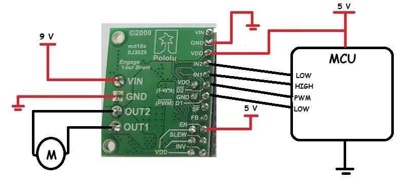
Hello. I have MC33926 Motor Driver Carrier…I want to use it with my MSP430F5529 Board…But really the usage information of this driver is very poor. I don’t understand how i will connect the pin to my mcu. Firstly i just want to turn the motor right or left with my mcu produced pwm signals. I draw my pins connection below. What do i need to turn the motor ?

Hi.
The first thing I notice from your diagram is that you are connecting two different power sources to the VIN pins. Those pins have the same name because they are connected to the same net. Connecting both a 9V source and a 5V source to that net has a good chance of damaging something, so if you actually connected the driver that way, it is possible that it is already damaged.
You will probably want to connect your 5V source to the VDD pin instead.
The MC33926 does have a fairly complex control interface, but we try to make using the driver easier by giving a list of the functions of each pin and some suggested connections on the driver’s product page:
Since you have two PWM pins labeled on the microcontroller in your diagram, it seems like this control scheme from the product page is the one you are interested in:
“The control lines can be reduced to two pins if PWM signals are applied directly to the two input pins with both disable pins held inactive.”
It is not clear from your diagram whether you have the jumpers that connect D1 and D2 to the GND and VDD pins next to them, but if not you will want to add those after connecting 5V to VDD.
By the way, if your 9V power source is a standard 9V battery, it might not be strong enough to run your motor. In general, we do not recommend 9V batteries for high current applications like motors, since they cannot output much current and have low capacity.
-Claire
Thanks Claire for your great explanation!
Firstly i just want to turn the motor to the right with controlling the pwm signal. So as your suggestion i connect my pwm to D2 and D1 to low and only for one direction control IN1 HIGH , IN2 LOW. I powered the driver on the Vdd pin with 5V. Everything looks fine? If you say yes , i will make it real… Thanks in advance.
M.Serdar Çelik
Those connections look fine. I did notice though that some of your solder joints (like OUT1) could probably use a little touch up. If you are not very familiar with soldering, this guide done by Adafruit might be helpful.
By the way, If you do not use the jumper that I mentioned to connect EN to the pin next to it, you do not need to supply 5V to the VDD pin. The VDD pin on the top right is only used to supply a voltage to the VDD pins on the inside row of pins. Giving it 5V will not hurt anything though, so you do not need to remove that connection.
-Claire
Sorry but i could not understand this sentence: "By the way, If you do not use the jumper that I mentioned to connect EN to the pin next to it, you do not need to supply 5V to the VDD pin. " Do you mean if i connect EN pin to 5V, it doesn’t need to connect VDD to 5V ? Right?
Yes, if EN is connected to 5V, you do not need to connect 5V to VDD.
-Claire