Hi!
Prelude: Admittedly I am a complete mechatronics novice (an am also new to these forums, again, hi!) - but hopefully that is soon to change. I am currently undertaking my first robotics project however, and am working with Pololu MC33926 motor drivers, Pololu 25D Metal Gearmotors and an Arduino 2560 Mega.
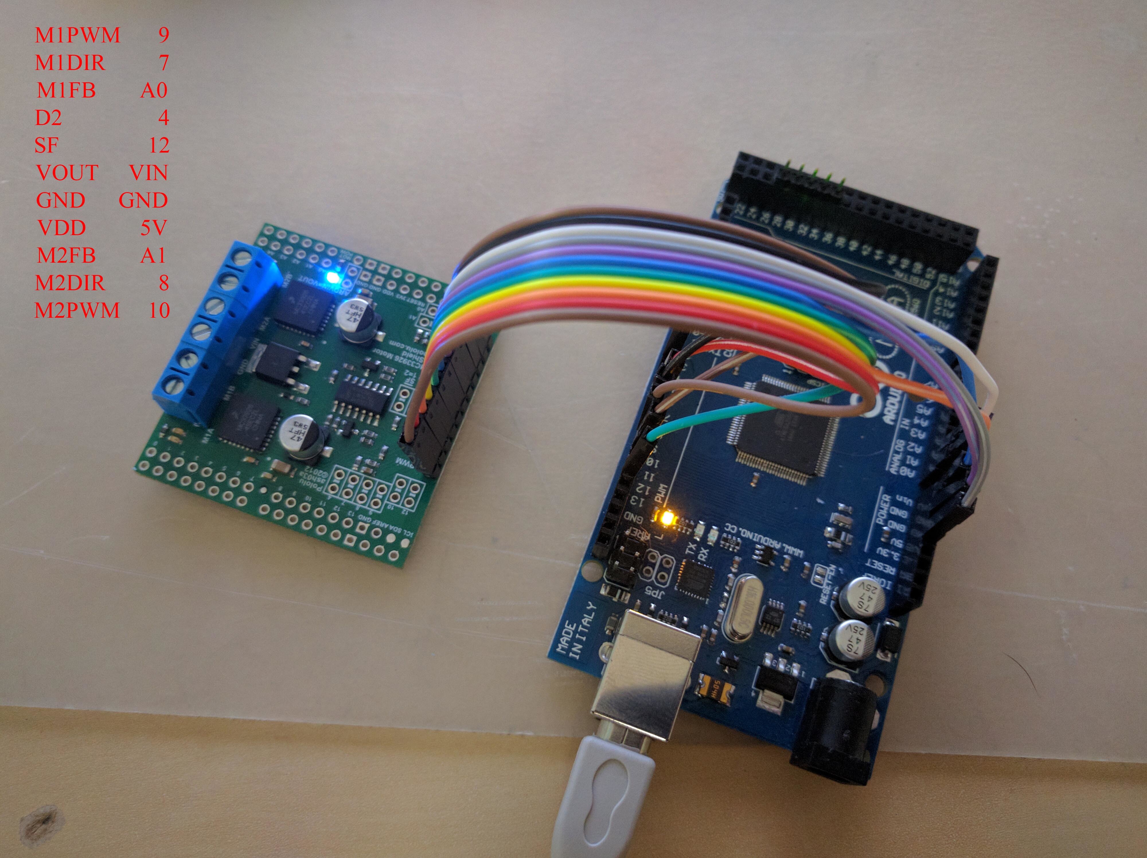
Problem: I am currently attempting to attain communication between two 25D Metal Gearmotors and the Arduino through one MC33926, and have thus connected the neccessary pins of the MC33926 to the Arduino, and have uploaded the Demo code provided by Pololu. However, the serial monitor displays a “Dual MC33926 Motor Shield fault” message, and so I assume I have wired the motor driver incorrectly.
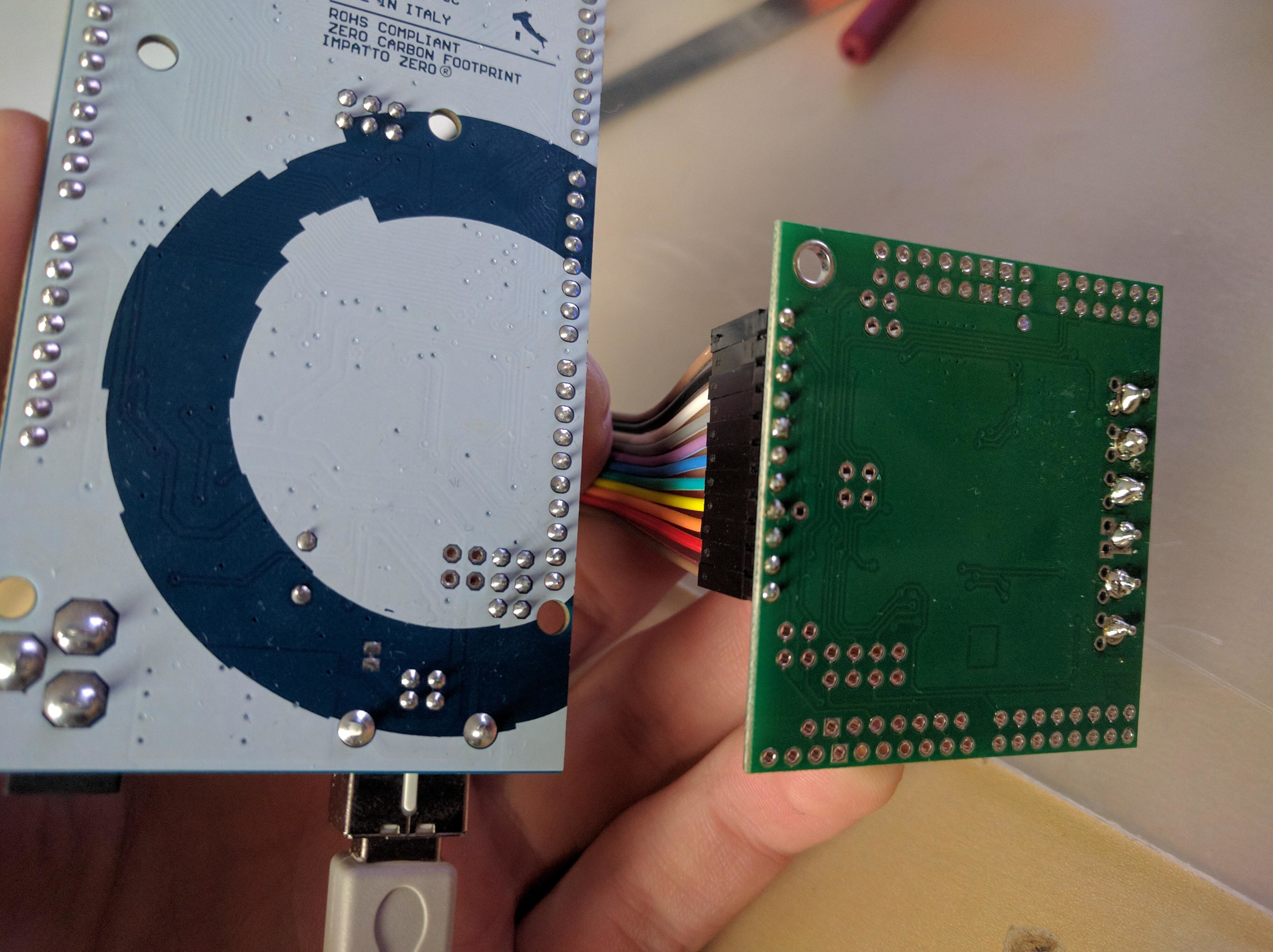
I would be incredibly grateful should an experienced user identify my mistake so I might begin to program for motor control. As such, I have uploaded 2 images which may assist. The first, MC33926_1, maps all the pin connections I have made. The second, MC33926_2, displays my first-time solder work, which may also contribute to the fault error. Feel free to ask for any additional photographs or information!
Please advise.
Edit: 5/5/2016 7:14PM (Adelaide, Australia)
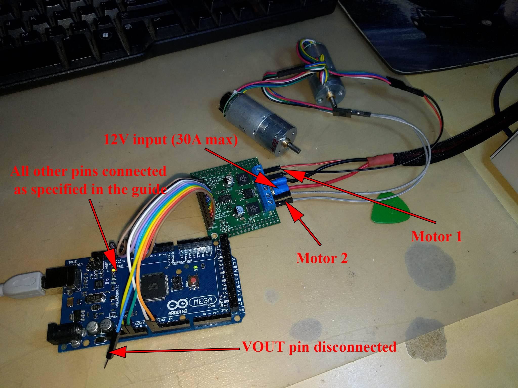
After further reading, I have disconnected the “VOUT” pin on the MC33926 and have connected a 12V power supply to the large VIN and GROUND blocks on the board, in addition to two 12V 25D Pololu Metal Gearmotors. The board is certainly supplied power, as the blue light over the words “MOT POW” lights up. However, no other lights show when the Demo program is run, and the only information provided to me via the Serial Monitor is “Dual MC33926 Motor Shield fault” every time the Arduino is run and reset. Below is a third image, “MC33926_3”, which displays the new hardware configuration. Note that at the time the image was taken, the 12V power supply was off, so the blue light on the board does not show.
3 Likes
Hello.
Thank you for including pictures and making your post clear and informative. I do not see anything obviously wrong with the connections shown in your most recent picture. Do you still get a fault condition if you remove the motors from that setup? What are you using as your 12V power supply?
The status flag on the MC33926 triggers on undervoltage, overcurrent, or overtemperature conditions. It sounds unlikely that any of those are occurring in this instance, and your connections look fine, so you might try touching up some of your soldering. The soldering on the logic pins in a little blurry in your picture, so I cannot tell if any of them look particularly suspect. A couple of the solder points on the larger pads on the opposite side of the board look like they could use some extra touching up to be sure they are not causing an issue. You might also try using a multimeter to do some continuity tests between the Arduino pins and MC33926 shield’s pins. If you measure the continuity using the unpopulated pins on the sides of the board (that are intended for using the driver as a shield), it should give you an indication that the soldering on the header pins is making a connection.
Brandon
Brandon,
Thank you for taking the time to respond - and for your excellent suggestion detailing the checking of each header pin via the shield connections.
To answer your initial questions, the power supply is a 12V 30A max supply which I borrowed from a 3D printer. Using a multi-meter definitely finds an output of ~12V, and the supply is often used as a quick charger for LiPo batteries and so definitely has no trouble supplying at least 6 amps of its rated 30. Feel free to assess the supply yourself here. At your suggestion, I also removed both motors but to the effect of the same fault.
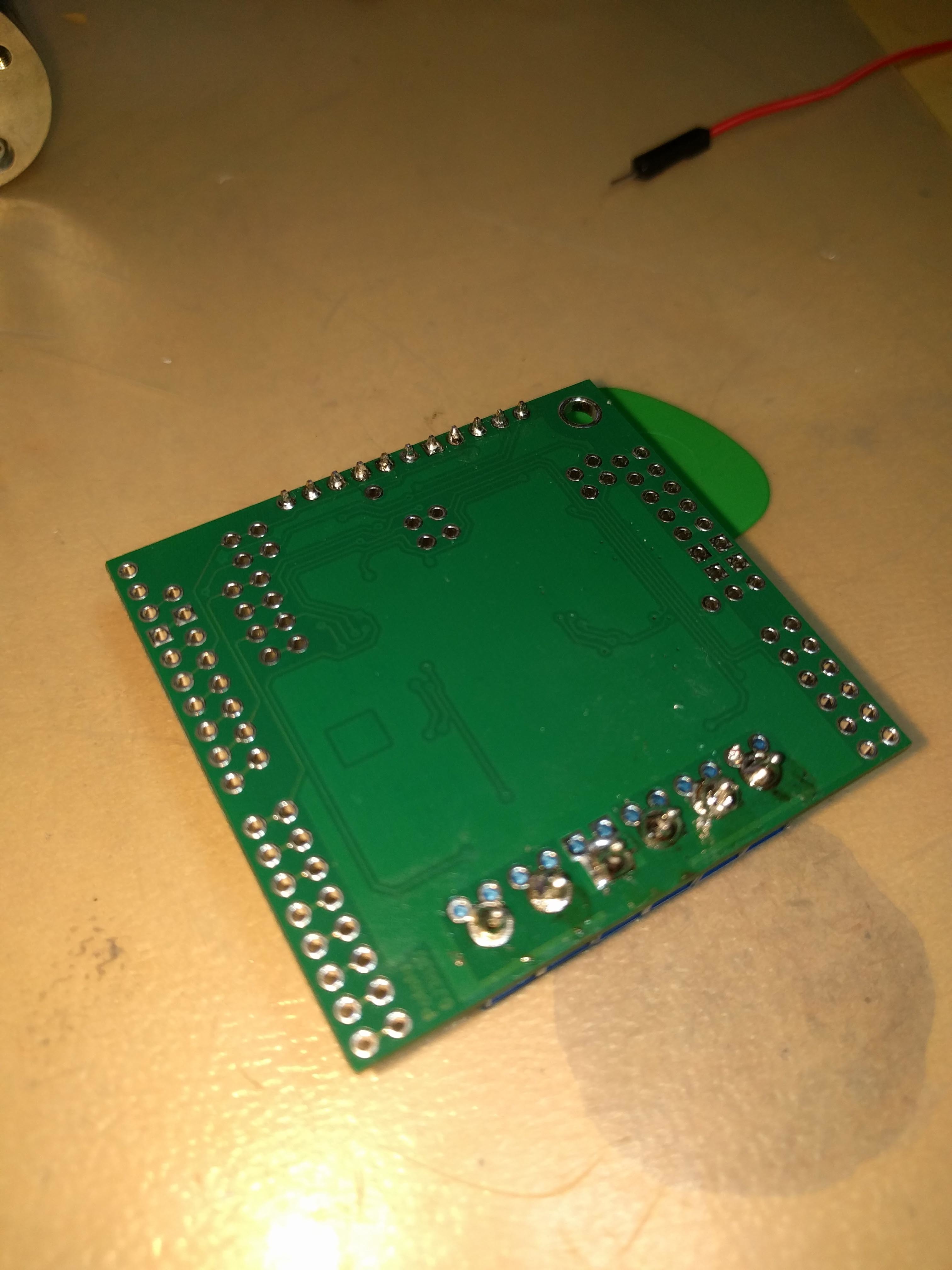
Checking each header pin for continuity against their corresponding locations on the board for use as a motor shield suggests all the connections are well. Additionally, checking the larger soldered connections against the screws in the header terminals suggests that these connections are also OK. Furthermore, I have uploaded a fourth image, “MC33926_4”, which displays my solder connections in closer detail.
Please advise.
Edit: 5/6/16 2:07PM Adelaide
I have had every pin examined and resoldered by a fully qualified Electrical and Electronics Engineer at my university - It’s still throwing up the fault though. How frustrating! Setup is as normal. I really am hoping it’s something I’m doing connection-wise - and I still hope it is something as simple as that - as with a less than two-week deadline on this project now, I’ll be damned if it’s the board itself.
Hello.
Thank you for the additional information. The soldering on the smaller pins in that picture look fine to me, and I do not see any reason that power supply would be a problem. In the email you sent us, you mentioned a second MC33926 shield that you were having problems with. Does the other shield have the same behavior in this setup? Are you using an unmodified version of the Demo.ino example sketch included with the library?
Can you try measuring the voltage on pin 12 of your Arduino with nothing else connected to it to make sure it is being pulled up, then connect the SF pin to it and see if it goes low? Also, could you measure pin 4 on the Arduino to make sure it is being pulled high and enabling the driver?
Could you try commenting out the while(1); line of code in the stopIfFault() function of the Demo.ino example sketch and see if the motor indicator LEDs on the shield function normally (without the motors connected)?
Brandon