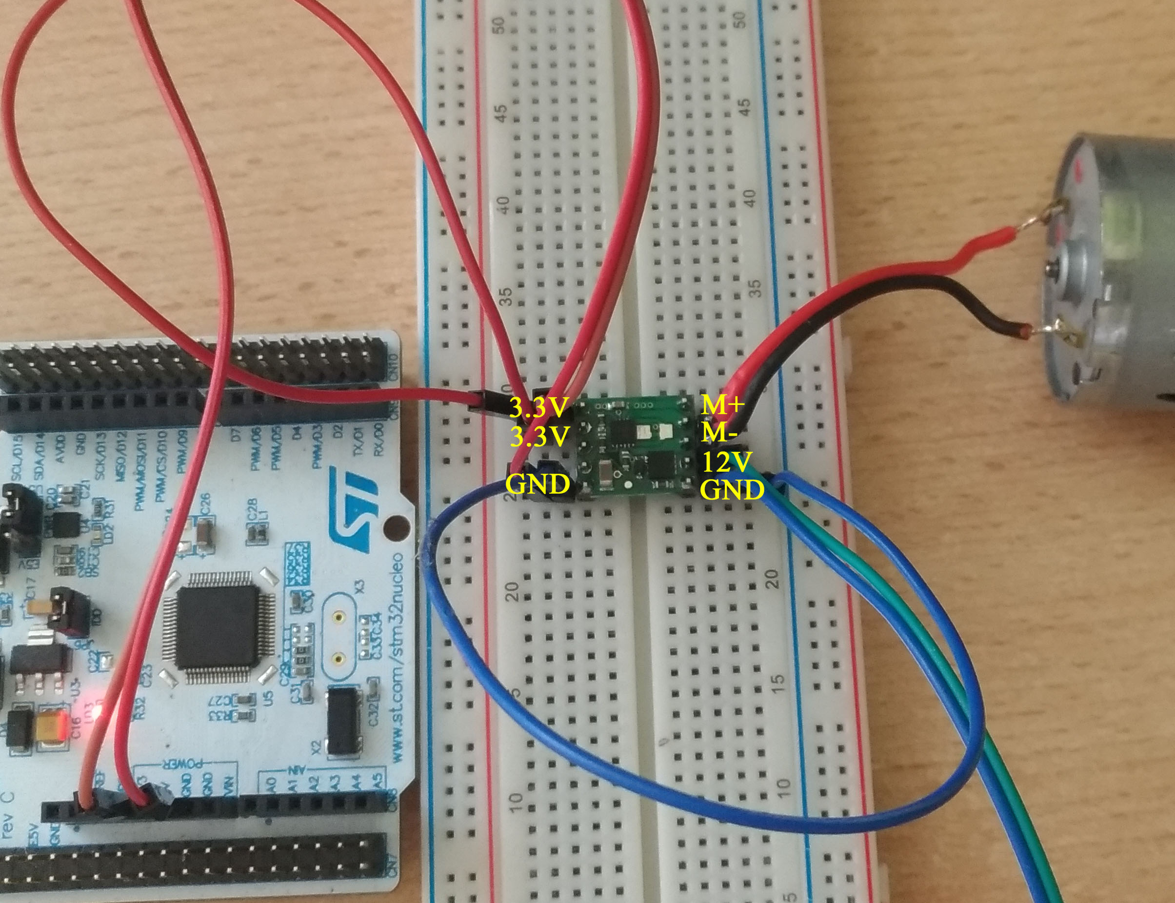
Hi, I bought this DC motor controller to drive my peristaltic pump, but was unable to make it works. I double checked wiring (I’m using Nucleo F401RE) and it just buzz and not spin, also the voltage on motor is smth around 0.5V (12V pover supply). PWM is connected to D9, DIR to 3.3V. Also all GND’s are common.
Here’s code
#include "mbed.h"
PwmOut PWM1(D9);

int main() {
PWM1.period(0.00002); // set PWM period to 0.02 ms
PWM1=0.50; // set duty cycle to 50%
}
Thank you for your help
Hello,
I am sorry you are having problems with your MAX14870 motor driver. Can you test the driver separately using logical signals for the PWM and DIR pins? Try applying 3.3V to both of the DIR and PWM pins to see if you get full speed in one direction. If that seems to work, you can apply 3.3V to the PWM pin and connect the DIR pin to ground to test the driver in the opposite direction. If your driver is still not working, can you post some pictures of your setup showing all of your connections? Also, can you post a link to your motor’s datasheet?
-Derrill
Hello,
so I applied 3.3V on DIR and PWM and nothing happened. The DC motor just buzzed. I tried another one 12V 3.6W and that didn’t move either.
Unfortunately for motor there’s not much. The closest model is this: (with some sort of datasheet) [DC motor ] (http://www.dx.com/p/chihaimotor-gb37-520-dc12-0v-85rpm-mini-gear-motor-silver-341395#.W2Fw9dL7RaQ)
Thank you for suggestions
Thank you for sending that link. Your connections seem fine; can you try removing the motor driver and testing only the motor by connecting it directly to your power supply to confirm it is working?
-Derrill
So I applied 3.3V and DND and 12V and there’s output of 12 V on M+/-. After I attached motor that dropped to 0.03V.
Getting 12V across the motor driver outputs is good, though the voltage dropping to almost zero as the motor is connected is not. It is sounding like this might be a power issue.
Can you link to a product page or datasheet for your 12V supply? How much current can it handle? Can you do what Derrill asked and try removing your motor from your setup and test it by connecting it directly to your power supply to confirm that it is working?
-Jon
As a source I use ordinary 12V AC/DC adaptor that can handle 2A. From data sheet of motor it should draw 1.1A maximum which I tested on DMM. Of course I tested motor directly connecting it to 12V and it spins without any problems.
Thank you for suggestions
It sounds like your motor could be drawing more current than the MAX14870 can handle. When stationary, brushed DC motors like the one you are using will momentarily draw up to their stall current in order to start rotating their output shafts. So, it sounds like the motor you are using could have a stall current that is higher than the peak currents the MAX14870 can handle.
One thing you might try doing is ramping up your motor speed by supplying a low or zero duty cycle PWM signal, and incrementally increasing it to a full duty cycle PWM signal over a couple seconds. You might also try limiting the maximum duty cycle.
-Jon
Maybe it’s possible. I measured peak current when motor was connected to 12V and It was 2.4 A which is really close to 2.5A peak motor current. I suppose there’s some +/- for that peak current right? So it can be 2.5 but also 2.4-2.6A? I tried 0% duty cycle and slowly increased it to 100% and nothing happened. I guess that means that I’ll need something a bit powerful?
Or can it be that I’m using 50 kHz PWM?
There might be some tolerance for the magnitude of the peak current that this board can handle, but since you were not able to run the motor even when the duty cycle was ramped up, that makes me less suspicious that it is an issue with the inrush current of the motor.
Can you try monitoring the state of the !FAULT pin while you are trying to control your motor? Note that this pin is an open-drain output, so you must use an external pull-up resistor to give this pin a default high value if you want to use it.
If the !FAULT pin never goes low and you still cannot control your motor, can you try replacing it with one that has a much lower stall current (like 1A), or a resistor (one that is around a few hundred Ohms should be okay)?
As a last-ditch effort, can you try checking the !FAULT pin like I described above by making your connections without using your breadboard? (It looks like you can use female to female jumper wires.)
-Jon
Can you try monitoring the state of the !FAULT pin
Yes I added pull-up resistor and when I connected motor it went to GND, after disconnecting again 3.3V.
or a resistor (one that is around a few hundred Ohms should be okay)?
I tried 200 Ohm resistor and it was absolutely ok smth around 11 V.
without using your breadboard
So I tried to not use breadboard and… noting… well !FAULT went GND again
Thank you for all suggestions. It’s a bit sad that it can work on paper with all datasheets but in real life there’s a problem. I guess I’ll have to buy something a bit powerful like POLOLU-1212 based on MC33926. It’s overkill but I guess that’s the only solution.
Since the !FAULT pin is going low when you try to control your motor, it does sound like it is drawing more current than the MAX14870 can handle.
Instead of the MC33926, we recommend using the newer TB9051FTG, which has similar performance (and less than half the price) and has a simpler control interface.
-Jon
Thank you for all help with this issue. Well I hope this:TB9051FTG will work because it’s not very easily available in my country and price difference isn’t that high. I’ll post here if I succeed.