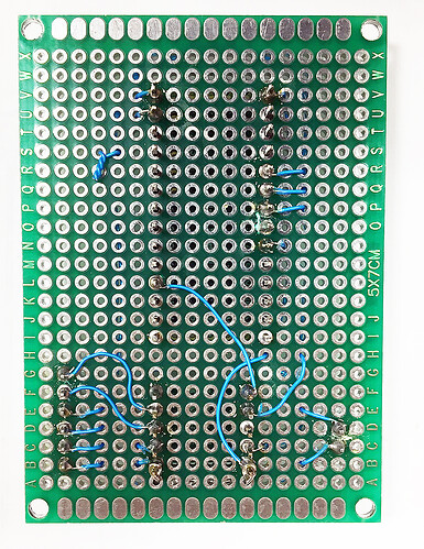
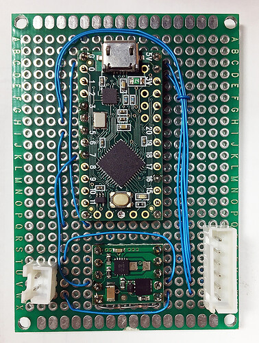
I’ve got a simple application, driving a DC gearmotor with the MAX14870, controlled by an Arduino.
Changing DIR state doesn’t work as expected. Set HIGH works fine. Set LOW motor shuts off.
PWM functions perfectly. I have double checked wiring, pinouts, etc. Any suggestions?
Here’s my simple test code -
#define PWM 16
#define DIR 5
#define EN 7
int led = 13;
int dutyCycle = 212;
void setup() {
pinMode(PWM, OUTPUT);
pinMode(DIR, OUTPUT);
pinMode(EN, OUTPUT);
pinMode(led, OUTPUT);
}
void loop() {
digitalWrite(led, HIGH); //watchdog
digitalWrite(EN, HIGH);
digitalWrite(DIR, HIGH); // setting LOW doesn’t work???
analogWrite(PWM, dutyCycle);
}
Hello.
Can you post some pictures of your setup? Specifically, can you include pictures that show all of your solder connections, how everything is wired, and how everything is powered?
By the way, the code you posted looks like it drives the nEN pin high, which would disable the driver and prevent it from operating in any circumstance. This makes me concerned you have either posted the wrong code or do not have the driver connected the way you think you do.
-Patrick
I just tried setting EN High, to see what would happen.
I should’ve changed the code back before posting it, to avoid confusion.
Anyway, I am a well seasoned professional. Soldering and craftsmanship is not an issue.
The device is wired precisely as shown in the application diagram.
Can you verify that your microcontroller is sending the correct signal and that the motor driver is receiving the correct signal by measuring pin 5 and the DIR pin with a multimeter? Could you also try testing the driver without a motor attached by measuring the voltage across the M1 and M2 outputs?
-Patrick
Interesting. As it turns out, the driver is working perfectly. Now, I have to figure out why this silly motor isn’t changing direction! LOL Thanks Patrick.
More mysteries. So, I did my most recent testing with the motor voltage input set down around 5V. And, everything behaved just as it should. But, my application is a 24V motor. There is wherein the problem lies. There is a motor input voltage threshold, around 23V at which the driver stops, when DIR is set LOW. When I lower the input a couple volts, it comes back to life. Ring any bells??
Just to confirm, are you observing this behavior even with no motor connected?
-Patrick
No. This is only with the motor connected. The motor draws about 160 mA Fwd or Rev. This driver is supposed to be good to 36V at 1.7 Amps, eh? Very weird.
I suspect you are triggering the driver’s overcurrent protection. What is the stall current of your motor? Are you trying to change direction while the motor is turning at full speed (i.e. going directly from full speed forward to full speed reverse)?
-Patrick
I thought that might be the case. That’s why I tested the two states separately. At the moment, it’s a no load situation. I’ll see if it works with a soft start ramp. I was going to do that anyway.
So, have RPM ramping up and down. Only works with DIR HIGH, if input at 24V.
Turned back down to about 20V, it wakes back up.
Motor has no load.
#define PWM 16
#define DIR 5
#define EN 7
int led = 13;
int dutyCycle = 212;
void setup() {
pinMode(PWM, OUTPUT);
pinMode(DIR, OUTPUT);
pinMode(EN, OUTPUT);
pinMode(led, OUTPUT);
}
void loop() {
digitalWrite(led, LOW);
digitalWrite(EN, LOW);
digitalWrite(DIR, LOW);
for (int i = 0; i <= 255; i++) {
analogWrite(PWM, i);
delay(10);
}
digitalWrite(led, HIGH); // PWM at max
delay(5000);
for (int i = 255; i >= 0; i–) {
analogWrite(PWM, i);
delay(10);
}
delay(5000);
}
I meant to mention that I also tried changing the polarity of the motor connections. Made no difference. DIR must be HIGH at 24V.
That is very strange. Just to make sure we are on the same page, I am going to list everything I think that we have established. Can you please check that my understanding correct?
- Using input voltages above and below 24 V without the motor connected, the driver works as expected in both directions.
- Using input voltages below 24 V with the motor connected, the driver works as expected in both directions.
- Using input voltages of 24 V or greater with the motor connected, the driver works as expected only if DIR is driven high.
- Using input voltages of 24 V or greater with the motor connected, the driver never starts moving the motor (even with ramping the input) if DIR is driven low. There is no voltage applied across the motor outputs, and switching the polarity of the motor connections has no effect on the result.
Can you try a simple experiment where you power the motor and driver with 24 V and just directly set the speed to 40% duty cycle (i.e. analogWrite(PWM, 100)). Do you get the same behavior of it working in one direction but not in the other?
I understand you are operating at no load, but can you still tell me the stall current of your motor?
Also, what Arduino are you using?
-Patrick
Statements 1, 2, 3, 4 are all true.
Setting the PWM to constant 100 has no effect when VIN >22V and motor connected. Only works DIR HIGH.
MCU is a Teensy LC
The stall current is unknown. No load is about 150mA. Commutator reads 5.7 ohms. Since ramping doesn’t change anything, I’m fairly dubious of back EMF as the culprit. Here’s what I’ve got on the motor -
That kind of coil resistance would result in a current draw of over 4 A, which is beyond the driver’s 2.5 A max, so you are probably tripping the driver’s over-current protection. What is the fault output doing during your tests? Can you send us pictures of your setup and oscilloscope screenshots showing what is happening?
-Patrick
Okay. Well, for lack of any other evidence, I’m left to believe the current is being overdrawn, though why that would be in just one direction, is beyond me - especially since changing the motor polarity has no effect. I haven’t polled the fault pin. And, I don’t own a scope. So, I guess I’ll be trying out a heftier driver. There’s nothing at all special about my setup. It’s just the one lone motor on this circuit, spinning freely.
Since the current path through the H-bridge is different for the different directions, the accuracy of the internal current sense will generally be different for the two directions. As such, there will pretty much always be some window of operation where current in one direction is read as above the over-current threshold while that same current in the other direction is read as below the over-current threshold. It seems like you have probably found that window.
By the way, you can get a decent scope these days for a few hundred bucks, so we strongly recommend you invest in one. It will save you a lot of time and give you better understanding of your systems, which enables better designs, better margins of operation, etc. Without one, you’re left mostly just guessing about what might be happening, which isn’t a great way to operate.
-Patrick


