Hello,
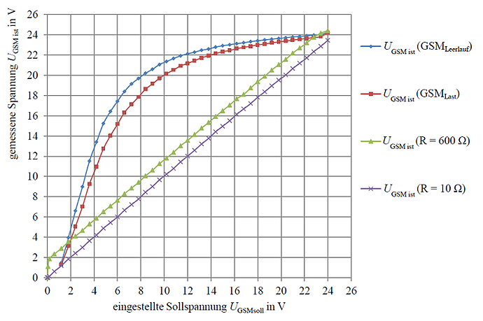
I’m using the motor driver Dual VNH5019. When tested under different loads, I have found that the actual motor voltage differs from the setted voltage (you can see that in the attachment). The x-axis represents the setted, the y-axis represents the actual measured voltage.
The measurement series are from top to bottom:
DC motor without load
DC motor with load
resistor with 600 ohm
resistor with 10 ohm
My supply voltage is 24 V at a maximum current of 5 A.
According to your instructions I would have expected a load-independent voltage.
Does the Dual VNH5019 run within its specifications?
Is there a possibility to use a load-independent voltage regulation or to improve the behavior shown in the chart?
Many thanks in advance for your reply!
Greetings,
Konrad Henkel

