I’m testing out the LVDS with the Mini Maestro and am having some problems setting the direction and speed. I can get it powered on and configured, but when I send a forward (or reverse) command, I’m not getting a response. I’ve tried different motor numbers and speeds, but no luck. I have not connected any motors yet and am just using the LEDs indicators. I’m sure it is a bone head coding error, but I just can’t seem to see it. Any help is appreciated. Thanks!
PS - if I reset the controller after the configuration, it goes dark…
OK, I got it working. I thought the second reset was tripping me up, but it was necessary. Just had to put some delays in. Here’s some code that works in case anyone else has problems. It’s rough but it works…
I still need to play with the delays to see how much is really necessary.
#configuration
reset
configuration

5000 delay
reset
5000 delay
# Main routine

begin

  forward

  3 get_position  #get value from distance sensor
  512 less_than   #threshold for reversing
  if
    reverse
#  else		#optional # can replace earlier forward command for
#    forward		# a more pure reverse, without back and forth motion
  endif

repeat


sub reset
  8000 1 servo
  10 delay
  0 1 servo
  10 delay
  8000 1 servo
  10 delay
  return

sub forward
  100 delay
  127 7 0 128
  serial_send_byte
  serial_send_byte
  serial_send_byte
  serial_send_byte
  200 delay
  return

sub reverse
  30 6 0 128
  serial_send_byte
  serial_send_byte
  serial_send_byte
  serial_send_byte
  2000 delay
  return

sub configuration
  100 delay
  2 2 128
  serial_send_byte
  serial_send_byte
  serial_send_byte
  100 delay
You should only set the configuration when you need to change it. Typically, you would have a different program for that to set up your motor controller, and it saves the settings internally. If you rewrite the configuration every time in your normal program, you risk burning out the motor controller’s EEPROM in which the settings are stored. (The memory is good for thousands of writes, but if you accidentally change some timing in your code and introduce some loops you weren’t expecting, you could potentially send hundreds of new configuration commands per second.)
Thanks Jan, I thought (I don’t know why) that I had to configure it on startup each time. Good to know.
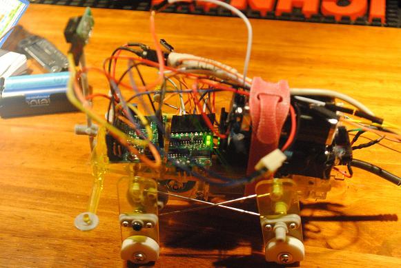
I have another question. I rigged up the 12-ch Maestro with the motor controller to a single motor “dog” robot from Tamiya. I’ll attach a picture of it. As you can see both the Maestro and the motor controller work. I have an IR distance sensor set to reverse the motor. It works without a hitch so long as there is no power to the motor. ie, the two green LEDs turn red once the motion sensor is activated. The problem I have is when I connect the power to the motor. The motor will power for about a second or two and then the motor controller shuts down. The Maestro blinks red (error) and the motor controller stays dead until I USB connect to the PC again.
It is only one motor so I don’t think it could be drawing too much current. I’ve tried different power configurations and also setting the Motor controller to both dual motor config and it is presently in the single motor config with the controller bridged.
Any thoughts as to why the controller is shutting down?
You probably have noise problems, which can be difficult to track down. The motors in the Tamiya kits are quite (electrically) noisy, so things like what batteries you use and the details of what wires run where can affect your results. In general, one of the easiest things to do is to put in a less noisy motor, such as this one:
OK, thanks jan. I thought maybe that was a cause, so I put a .1 uf across the leads of the motor. Thanks for the link though; I suppose I’ll try the triple capacitor method.
It’s unlikely that it’s a matter of the motor controller not handling. If you want to pursue this further, can you post a schematic and a picture of your cleaned-up wiring? Do you have access to an oscilloscope?
Unfortunately, no oscilloscope. I had thought about getting one of $200 ones, but wondered if they were any good?
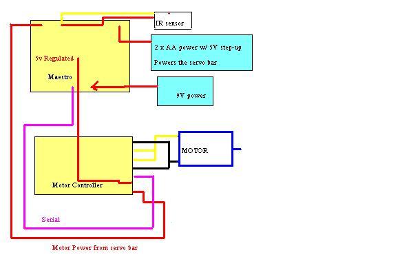
Anyway, the good news is I got it working. However, I am now using 3 different power sources, which is too heavy. I don’t know why only using 2 power sources was causing the robot’s motor controller to malfunction.
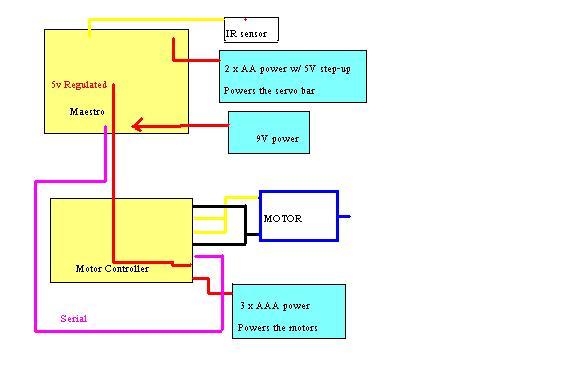
Do you have any recommendations on how to power it? I will attach 2 diagrams, one with the 2 power sources (which was malfunctioning) and the other diagram showing the new config with 3 power sources.
I’ve got a 9V supply to the Maesrtro. I then use the Maestro’s regulated 5V output for to power the motor controller. The AA 5V step-up powers the servo bar of the Maestro, which powers the IR sensor. The AAA 3.6V powers the motor line of the motor controller.
EDIT I didn’t bother to draw them in, but all of the devices are grounded to each other.
I would love to power this with just one power supply, but I keep getting malfunctions when I try anything other than the 3-supply configuration. (For instance, I tried feeding the motor supply from the servo bar [powered by the 5V-AA]). I have the following at my disposal:
How confident are you that your motor diagrams above are accurate? Is there any chance you’re actually powering the motor controller with your Maestro’s regulated voltage?
It seems like your power scheme could be much simpler. Why not use 3 AAs for everything?
3 AAs => motor voltage (VMOT)
3 AAs + adjustable boost regulator (at 5 V) => Maestro VIN, Maestro servo power, and LSDSMC VCC
I am a bit worried about putting servos on your LVDSMC logic power line, however. You might want to put a decoupling capacitor across VCC and GND close to the motor controller, and you might consider using a second step-up regulator just for your LSDMC logic power line if you notice power problems that seem to be triggered by the servos.
Thanks for the suggestions. To clarify, yes, I am sure the motor power is not connected to the regulated power from the Maestro. Also, there are no servos here. The only thing on the servo bar of the Maestro is the IR distance sensor.
I tried using the 3AA with the adjustable regulator at 6V. I also substituted in one of the 6V motors you sell at Pololu. I have the 6V line split between powering the VIN of the Maestro and the VMOT of the LVDS. The regulated 5V from the Maestro powers the VCC of the LVDS and the IR sensor. Simple enough, but I am having the same problem. The little robot works for a few seconds, then the LVDS shuts down, especially if the robot reverses direction on the motor.
The reason I am wondering if it is some kind of power source problem is because if I take the exact same configuration described above but alter it only so that the VMOT power comes from a second power supply, it works beautifully.
Problem is, as a walking-ish type of robot, the extra weight of a second power source is a fatal flaw. If you have any suggestion, I would greatly appreciate it!!
I tried increasing the voltage to the Maestro to about 10 volts, but still no luck. It seems like the 3AA batteries just cannot produce enough current to run the Maestro, LVDS, IR sensor and motor at the same time. Is this right?
If you haven’t tried already, I suggest you attempt this setup:
3AAs powers motor driver directly, and then powers the maestro from a 6V boost. The 5V output of the Maestro powers the IR sensor and logic power input of the LVDS. Put a ~22uf cap on the 5V power lines next to the IR sensor, as they can be noisy.
3 alkaline AAs can’t provide much current, but it should be enough for one motor two small boards and an IR sensor. NiMH batteries would be better.
Another good question for the Pololu guys: Is 25mA (~50mA from Maestro, minus 20-25mA for IR sensor) enough power for the motor driver logic?
Yeah, I tried that configuration, but no luck. Esp when the controller reverses direction for some reason. But, of course, with 2 separate power supplies, it works great.
I’ll try your suggestion of a cap on the IR sensor. Also, maybe I’ll try replacing the IR sensor with a push button to see what happens…
Did you try Ben’s suggestion of 3AA directly powering motors, then boosted 5V power everything else? You can put 5V to the Maestro’s vin pin. Even if the outputs were not quite at 5V, it’s not a problem as microcontrollers are designed to handle a slight overvoltage (around .5V for PICs I believe) on their inputs.
It would be a good idea to test this without the IR sensor, as that eliminates the possibility of extra noise.
As a side note, increasing the boost voltage will make the problem worse. For the same current at higher voltage, the batteries have to provide more current to the boost. Essentially, higher current gets turned into higher voltage, but since you are regulating the voltage back down anyway, all that excess current gets turned into heat.
So, the update is that I replaced the IR sensor with a push button and I still have the same problem. Using the LED lights on the LVDS as indicators, it seems to work fine. But, when I connect the VMOT line directly to the 3xAA source, things get erratic and then, in short time, the motor controller shuts down.
Hell, if possible, I’d even post a video. I was hoping to get this figured out by 12/26, when I have come up with a gadget to demonstrate at a family reunion.
Edit You are absolutely right about not increasing the voltage. When I increased it to 9V, the problem only got worse.
Have you tried rechargeable batteries? It sound’s like the batteries simply can’t supply the current to both the motor and boost at the same time.
Here is an odd suggestion to try. Use a 2cell AA and a single cell AA. Also, switch back to the original motor that came with the Tamiya kit, which runs at 1.5V (right?). A 1AA and 2AA holder together shouldn’t weigh to much. The single AA powers the motor, and the 2AA powers everything else through the 5V boost. You probably wont get great battery life though…
Early on, I tried the 2xAA w/ 5V boost, but it could not power the Maestro, LVDS and sensor together. However, I like your idea. I CAN confirm that it works with a 3xAAA and a single AA (With the stock motor). I’ll have to try and load it all on the robot and see if it can handle it. I hope so, but all the “stock” robot carried was a single AA…
Oh, and yes, they are all rechargable batteries. NiMH Eneloops.