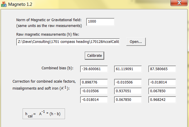
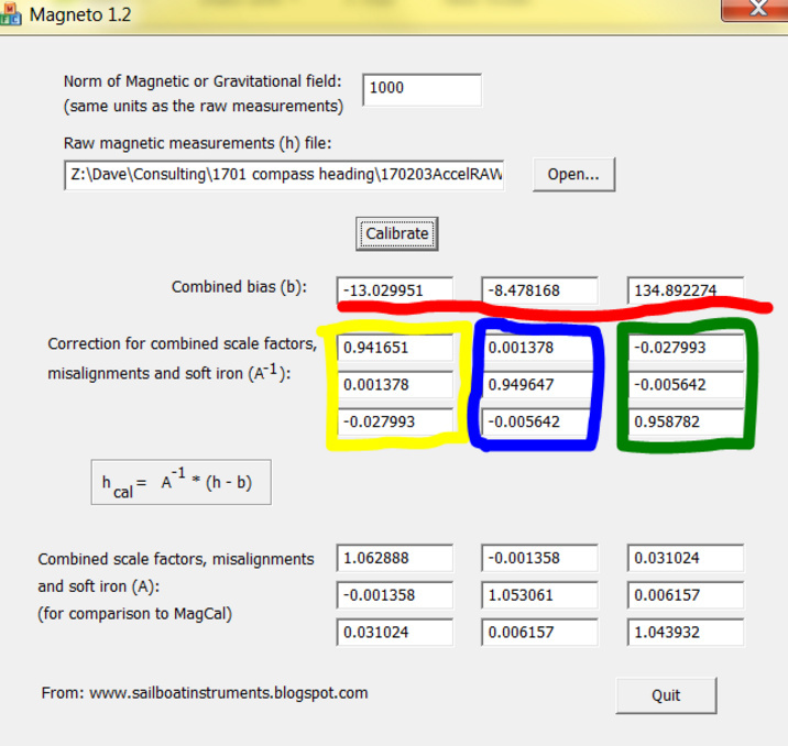
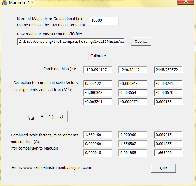
here is the magneto output AFTER calibration:
Compared to the values [20.959833, -31.234477, - 106.387816], it is still not what i would call ‘close to zero’ for the combined bias, but let’s press-on…
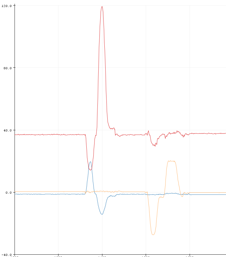
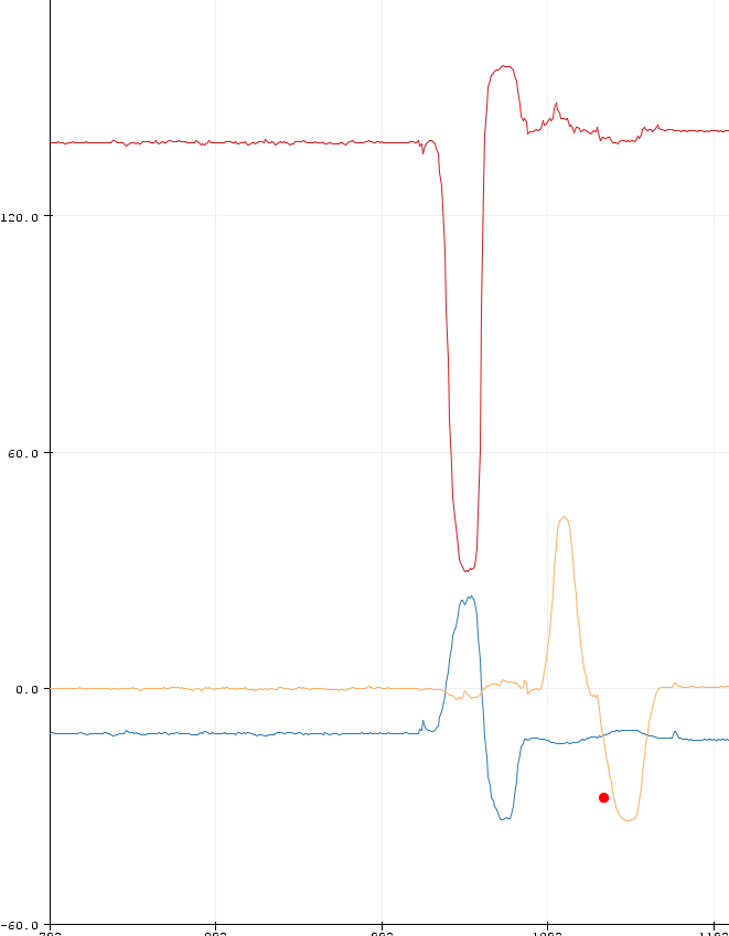
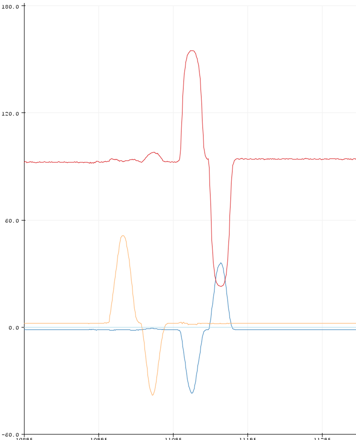
HERE’S THE RESULT:
Legend: red=heading, Blue=tilt, Yell=Roll
I kept the heading absolutely CONSTANT (in my wooden gimbal) . then
a. moved ONLY tilt (blue) up20deg, down 15deg. then back to neutral
b moved ONLY roll(yellow) right20deg, roll left 20deg, then back to neutral.
i never touched the heading, so the red should stay perfectly the same but as you can see it is LESS stable than before i ‘calibrated’ it!!! WTF. it ran better outta the box without calibration. I’m getting pretty frustrated with the LSM303D right now.
The accelerometer is clearly not calibrated correctly.
You have up to 10% errors in the axial gain values (the matrix diagonals) and the offsets are too large. It looks to me that you have run the raw accelerometer data through Magneto, not the corrected data.
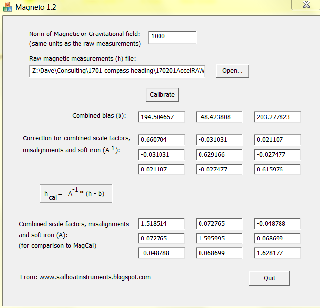
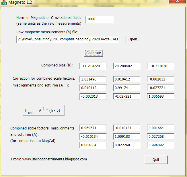
OK. thank you for the feedback. i have re-run the accelerometer calibration
a note: i think when i did the calibration the first time i ROTATED the device in all directions as you do with the compass calibration, but i did not JOLT the compass in all directions. This time, however i JOLTED the device instead. (Its an accelerometer test, after all)
the arduino forum notes say about this step to “… check if bias decreased.” . hmmmm well they have changed substantially, but i wouldn’t say they were close to zero. Anyway lets see if the tilt compensation is any better.
NOW TO THE HEADING, PITCH & ROLL SCRIPT AGAIN:
As before i am keeping the heading (red) constant. and then
moving the pitch (blue) up a bit then down a bit then back to middle, then
moving the roll left a bit, right a bit then back to middle:
As before the red should stay exactly stationary for a tilt compensated compass:
This is ANOTHER very poor result from the LSM303D. Because the values are consistent, my hunch is that it is still a calibration issue. BUT sheesh! What am i doing wrong???
Jolting is not the way to calibrate the accelerometer. Calibration relies on the presence of a constant acceleration, which in this case is supplied by the force of gravity. In the case of the magnetometer, it is the local value of the Earth’s magnetic field.
For accurate calibration, you need to be very careful to hold the accelerometer still while making each measurement, so it is quite a bit more finicky than the magnetometer.
That said, I don’t understand your plot. It seems possible that at some point, you are crossing a boundary of 90 or 180 degrees, and the math is failing because of sign ambiguity in a sin() or cosine() term.
OK thank you @Jim_Remington for the feedback - my mistake on the jolting, (I assumed i needed maximum readings) but no worries.
Before i get to the calibration re run:
Your comment “I don’t understand your plot. It seems possible that at some point, you are crossing a boundary of 90 or 180 degrees, and the math is failing because of sign ambiguity in a sin() or cosine() term.” I’m not sure WHERE in the plot you see this happening. I guess it is possible that i have sign ambiguity , though i have copied and pasted code, so it seems unlikely) but anythings possible, right?
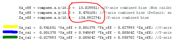
So while we are discussing the +/- signs, and to confirm:
for the first three boxes in magneto I have been SUBTRACTING from the equations, and
the next nine boxes i have ADDED.
Wherever there are two negative, it becomes positive
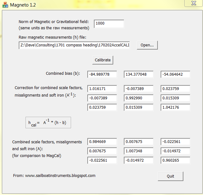
RE-DOING THE ACCEL CALIBRATION AGAIN
This time I have held it still and just ROTATED it in all directions (as with compass calibration) and re run accelerometer calibration once more. The results are below:
the re-run with the eqtns copied across. As before read is heading which i hold constant (via my wooden gimbal) then i only move pitch and then Roll
-i move Pitch (blue) forward, then back then return it to neutral
then Roll (yellow) to left a bit, right a bit and neutral
see below:
The heading of the device stayed the SAME and should not change at all. but the output (red) changes markedly.
arggg. What to do next>???
I’m hapy to try testing, changing the +/- signs, but there are multiudes of combinations to try. Where to start? There MUST be a logical solution to this!!!
Question: why is the dividing factor of 16.0 used to scale the accelerometer data? It is not needed. Has that factor always been there, before and after calibration?
Assuming that you have always included the factor of 16, it looks like you are applying the correction matrix and offset correctly.
However, the pitch correction is simply wrong. There must be a fundamental definition or sign error somewhere else – in the definition of the positive direction of the X, Y, Z axes and their association with the pitch roll and yaw axes, the definition of the positive direction of the pitch angle, etc.
sixD, a couple of things.
The Accel and Mag testing to be done correctly should have the IMU fixed to a non magnetic axle (horizontal to the floor, with some means of turning and indicating a equal distance set amount ) and rotated say 24 time (equal steps) around 360 degrees(also away from mag influences). As an example the X axis should point in the direction of the axle. 24 measurements for Mag and Accel are done seperatly but both done while X axis is in this position. Next the Y axis along axle same measurements again, two lots, 1 mag, 1 accel.
Last axis Z, is done by putting the imu on its side, the the z axis now parallel with the axle. Mag, accel , 2 lots of separate data. The 3 lots of separate data for each axis are then all put together as 1 lot of data, 1 for mag, 1 for accel. By using the axle, is how you get the accel without any other forces acting on it.
Photo attached showing cal device and IMU in Z axis test position
Jim says to yous the average for the norm, but Merlin says to use the highest positive reading in your un calibrated data as the norm.
This all takes a bit of time and you need some code to be able to take a averaged sample at each of the equal steps around the 360 degrees.
In the above code l supplied l didn’t un comment that divide by 16 (>>4,(bit move 4) same thing) as the IMU has a 16 bit Accel not 12 which is what that dividing was there for on the older IMU.
Also remove the (1000/1100.0) from the mag, this is also not required (also not un commented) as this is only required if wanting to get a mag field strength back as some data.
I have confirmed that this code works correctly to Merlins Magneto correction data, centreing and making the ellipsoid a circle (also retested with Magneto and with not so good cal data (done by waving around) within <1.2 %
You should have also found that the heading is increasing counter clockwise instead of CW, is this the case?
BUT going CCW tilted to 45 degrees my worst results are left tilt -4, R +5 using min,max cal my IMU was -13,+12 ( CW left +7, R +5) spreed-sheet attached.
Here is the code for CCW (standard code) with Accel scaling (also accel sign for nose up +, right wing down +) and CW heading line 79,80
Jim, could you have a look and see why CW has totally different results.
I have tried changing the signs all over on the mag, only were they are has a reasonable result been able magneto corrected CCW in shed.xlsx (11.7 KB) jim.ino (5.9 KB)
sixD, why did you change the alpha constant so much, you will be getting very little sample average?
Correction the latest code is Nose up -, if sign changed to nose up positive Line 44, the pitch becomes unstable like sixD has.
yes. the scaling factors are there both before and after. they were from the code in ://forum.arduino.cc/index.php?topic=265541.0. i know now they are not needed unless you need actual absolute measures (which i dont, but they are there both before and after, so no harm done)
Thanks, i did that. i dont see any issues with that.
I am unsure which sign to change. Do you men within the equation for Xa_cal, fxa or the equation for Fxm_comp?
thanks also to @kevin1961 for the information and picture. i dont have it on ‘an axle’, but instead in a wooden gimbal. I’m thinking that this should be ok. but what i have NOT tried is 24 separate static compass, then accel measurements. INSTEAD i am taking 100s of measurements (1000?) i have been carefully rotating the device as @kevin described i.e. the imagine you are painting the inside of a sphere (and described at sailboatinstruments and the underwater flow project - all linked above) and recording data every 150ms. … It’s how i got the ‘oval’ at the start of this thread and how i understood the calibration data was to be collected.
simply to ‘smooth’ the results. it just affects the filter. not the calibration.
this is my line 44: fYa = Ya_cal * alpha + (fYa * (1.0 - alpha));
do you mean the ‘-’ infront of the alpha??? this is just part of the filter and i dont think will affect the tilt-compensation.
NEXT STEPS
Thanks for the input so far. Next step is to adding to the code an uncalibrated output alongside calibrated ouptut i.e. running concurrently, so i can try to isolate the problem. and hopefully which of these +/- should be swapped.
I think if you look at it, increasing the constant decrease sampling and makes for a faster result, as per comments in my code.
Also sign change is re my code.
Is your heading increase changing positive CW or CCW
How can you paint the inside of a sphere and have the IMU stationary to be able to get the Accel data?
Perhaps this is the issue… when i am doing the accel calibration, i am HOLDING the unit (on its wooden thing-o). this means there is always some movement. it is not stationary, PLUS i am taking constant readings. i understood that was the way to get all the data for magcal software i.e. pretty much the same as was done for the mag calibration.
is this correct? if not, can you kindly point me to where in any of the info, datasheets, posts, blogs or other that it says to do this… if so i have obviously missed this critical detail.
sixD, it is in the blog, you just need to correlate what is happening.
But in saying that, l was confused on how the axis was rotated and asked questions to Merlin.
If you look at his plots of the accel and mag you will see all his data is at the outside of the circle/sphere, which tells you he is ONLY taking the data when IMU is rotated about its axis and not being waved around. We are not interested in data inside the max/min of the axis.
Same as waving the IMU around, we are trying to get max/min not all the other data, hence why Merlin says you need to rotate the axis 360 for each axis and you WILL then have the max/min to put into Magneto.
You will NEVER be able to do accel cal the way you are doing as you MUST have it stationary with no movement when taking the samples.
24-36 separate stationary measurements are required, Merlin says 24 is a good number (that’s what he uses)
In the photo showing my axle bucket, this was not the actual system l used.
The difference being l had holes in the side of the bucket which l feed the axle through which acted as a tight bearing l rotated around the imu around.I had a plastic toy wheel and used the treads as the equal measurements indication, in my case 25 inputs.
You also need to have a sample averaging when taking the measurements as per Merlins blog
Please answer in what direction your heading is increasing CW,CCW?
when the pitch value decreases the heading (the red line) increases = CW (and the reverse is true, too!)
Accel calibration: The taking of stationary readings:
OK so i am clear, when i take these 24-36 stationary measurements - from your photo on the plastic bucket - i take it this is only in the horizontal plane (i.e. heading changing and pitch and roll = constant) OR is this 24-26 stationary measurements in EACH of heading, pitch and then roll?
sixD, you seem to be only focused on pitch and roll (admittedly you have bad pitch tilt error) my question has been, does your HEADING increase when you rotate (maybe l should have said TURN) the IMU CW, CCW, in which direction gives an increase in your YAW heading (i.e turn through 360 degrees on the horizontal) .
Sort of, the data is re-mag and accel has nothing to do with heading, pitch, roll as such, because the Mag can’t do pitch and roll and the Accel can’t do heading, we are after the X,Y,Z of component,
If you look at the formulas you will see only X,Y is used of the mag to get a heading (North reference, albeit it could be miles off and is as good or bad as it is, it is Magnetic North (not true North).
Then the Accel is used to compute a tilt compensated Heading (Yaw).
So take the averaged sample at each data point which is a equal distance around 360 on EACH AXIS .
Re Bucket,I fill the bucket with water so it has some mass and won’t move.
So you change the position of the IMU axis after taking all the data on 1 axis.
Start by putting the X axis inline (the arrow on the IMU), in the direction (parallel) of the axle (axle is horizontal at all times) (doesn’t matter if it is pointing 1 way or the other down the axle (but better to be consistent), take averaged sample (Merlin takes an average over 64 samples) per lets say 24 different equal segments around 360 rotation.
Remove IMU and place the Y axis along axle, same as above (keep the arrow direction on the axis the same to alleviate any confusion, but l believe it doesn’t matter nor does the direction of rotating the axle)
Z axis, take notice as per my photo and the different position of IMU, so that the Z axis is now pointing down the axle (parallel),.
Merlin holds his IMU with a elastic band l have taped mine onto the square wooden block.
You now have separate Mag, Accel data to put into Magneto. Use the highest data reading for the Norm (although l believe any figure except 0 can be used, but why not use what the man who designed uses if not after a Mag Field output).
Hopefully now you should have a reasonably tilt compensated heading.
Keep in mind this cal should be redone in the finally location of your IMU in the boat.
Regards Kevin
thanks again for your reply and for sticking with this. i have decided that when i’m done i will pool together what i have learned as a summary so the next person can get there faster!
ahh. as i rotate CW, the heading number increases.
regarding you description of what to do… FANTASTIC. i wish i’d known. it is pretty involved, but ive come this far, i’m not stopping now!
last clarification. you say
[quote=“kevin1961, post:55, topic:11611”]
You now have separate Mag, Accel data to put into Magneto.
[/quote] but i understood we were only getting Accel. data here. i.e. for mag we did previously as the DYNAMIC all directions… “imagine you are painting the inside of a sphere” taking 100s and 100s of readings ‘on the fly’. i kow now that the Accel readings are taken staionary, but what you have said makes me think we do the BOTH Mag and Accel a) stationary and b) at the same time.
@kevin1961 can you confirm if you mean do both or just accel with this method pls.?
ONWARD…
i’m wondering now what is the best way to make sure each of the movements are EXACTLY equal segments around 360 rotation. your bucket of water is a good idea for stability, though getting the angle right will be hard. hmmm. …i’m thinking a big flat piece of ply with timber pointer (like a monster clock hand) and divisions geometrically drawn on the board. oh my.
I keep saying you need to do this for the Mag and Accel. I do the Xaxis Mag, then while it is on the axle l do it again for Accel, then change the position of the axis.
If you want to do it properly you need to do the mag and accel the same way. Doing it this way you get the sample AVERAGED reading for each point around the 360.If you read Merlins post he doesn’t say to do the Mag cal by waving it around, he invented Magneto so why not do what he says.
As l have shown with my tyre, anything with equal distance segments will do, so yes, what you propose will work, just do 24 (15 degree) segments as per Merlin (you must sample average the readings).
I have just been informed by my guru, that the norm for Magneto doesn’t make any difference as the scale factor is corrected for with the sin, cos in the formula, but it would be better to use a norm that gets the magneto closer to 1.
Interesting that your heading is increasing CW, were mine was CCW. Have just been told l have the signs in the wrong place to correct my direction. You need to use the right hand rule re mag field direction to get the correct signs.
[quote=“kevin1961, post:57, topic:11611”]
I keep saying you need to do this for the Mag and Accel.
[/quote]ok, ok. i get it now. i had obviously got some wrong ideas from before i was slow to realise the game is different now. thanks. [quote=“kevin1961, post:57, topic:11611”]
Interesting that your heading is increasing CW, were mine was CCW.
[/quote] yes. i suppose it just depends which way up the board is, yes?
Progress:
alright i have re-made my wooden gimbal ready to get these readings and i have written a tailor-made script for gathering, averaging between each move.
but i have just realised that this means i will get three ‘sets’ of (either 24 or 36, i’m using 36) 36 separate Mag and Accel readings : one ‘set of readings’ each for the board oriented in:
the X-direction
the Y- direction and the
the Z-direction
QUESTION: when i want to then go to MagCal, what do i do with these three ‘sets’?
i guess that i:
merge all the Mag readings for X, Y and Z LSM303D board orientations into a single tab-delimited text file for Mag (i.e. it will have 36 x 3 = 108 lines of three columns being for Xm, Ym and Zm) and
then merge all the Accel readings X, Y and Z board orientations into a single tab-delimited text file for Accel (which will also will have 36 x 3 = 108 lines of three columns being for Xa, Ya and Za)
Only then i use these two files in MagCal, One at a time each for Mag calibration and once for Accel calibration.
Yes and NO, it does matter which way up the board is (but this is your preference, as well as in which direction the IMU is pointing, have a look at the ARHS and the direction sign formula), but you can change the direction by using -1* against the axis but you need to keep to the right had rule, but l am currently having problems with the amount of tilt error, currently l would be happy with the error l have CCW, but when l change to CW the tilt error has increased by at least 50%, so still playing.
As l have said in my previous post (again, ha ha) . Yes like you describe You will have accel X,Y,Z (3 lots of 36 = 108 of data) same for Mag which l copy from serial monitor to Notepad.
Then import to excel via Data/from text/accel data(your data file)/lmport/delimited/next/tab,coma,space what ever you have to get rid of to get clear data/ Finnish
Then you can copy back to notepad to do Magneto and also do excel scatter plot for your data and confirm uncal to cal and see that it has centred and made a circle.
Could you post here your script please
Merlin uses 24 so there is no gain only more work in taking 36 sample points.
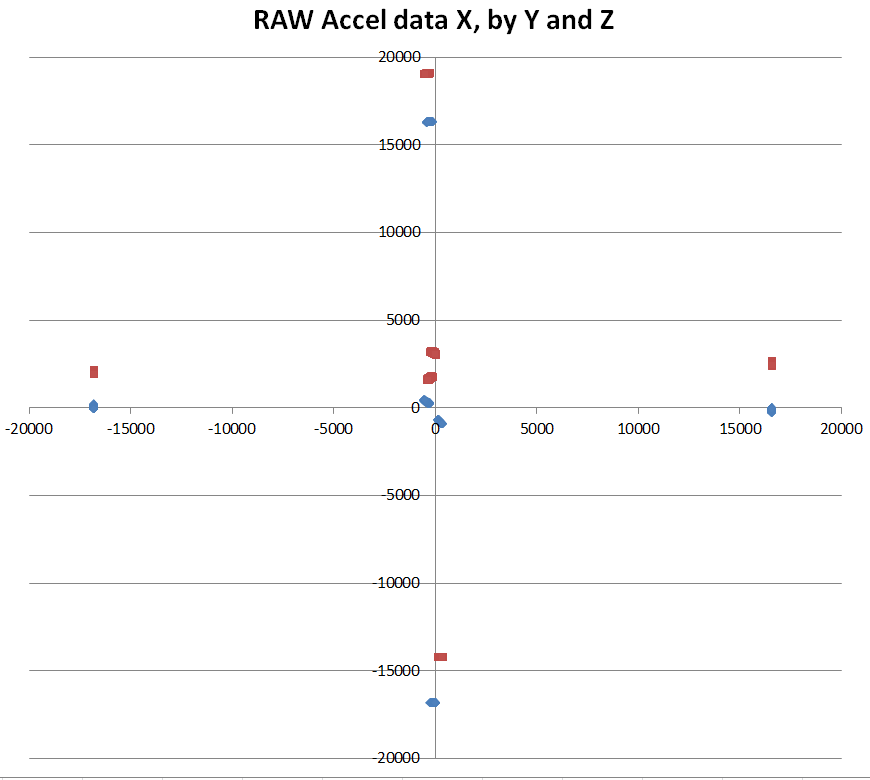
i have run obtained the six sets of raw data (based on the 6 directions of the LSM303D and then doing 36 equal divisions in a full rotation. (note: To keep this post from getting too long i will post the code for data averaging requested @kevin1961 separately after this one)
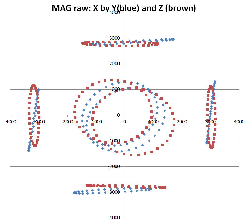
here is a scatter of the RAW (pre-calibrated) Mag data
The values affected by gravity for each orientation are in the order of ~16000, so let’s zoom in and look at the spread of those middle ones. (here is the same data with max and min constrained to 4000):
As before i keep the heading constant so the red line (heading) should stay flat as i move first the roll(yellow) and then the pitch (blue). You can see it is a little better than it was for the roll but is USELESS on the pitch tilt compensation, as you can see!
I will add that the heading - if kept on the flat - is now VERY accurate. i.e on my compass rose a real heading 184deg returns the right value now. So that is some progress
BUT FOR TILT-COMPENSATION THE LSM303D = UNCALIBRATABLE …WHAT ON EARTH SHOULD I DO NOW???