LSM303D tilt compensation problem

here is the data-gathering script “Multi-Sampling” for the 6 device orientations and 36 equal angle full-circle rotation that i wrote and posted as requested by @kevin1961 :

 /*
 * Multi-Sampling written to gather necessary data for LSM303D
 * for unit calibration.
 * 
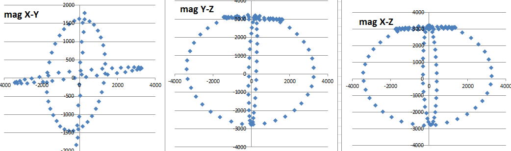
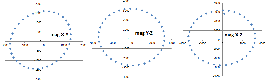
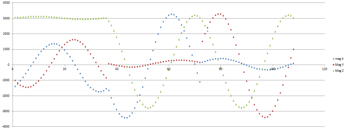
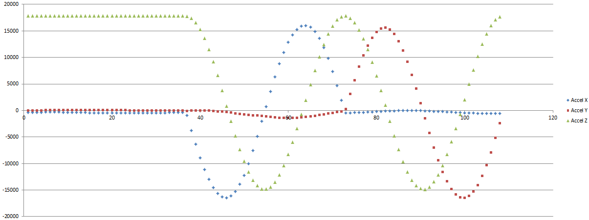
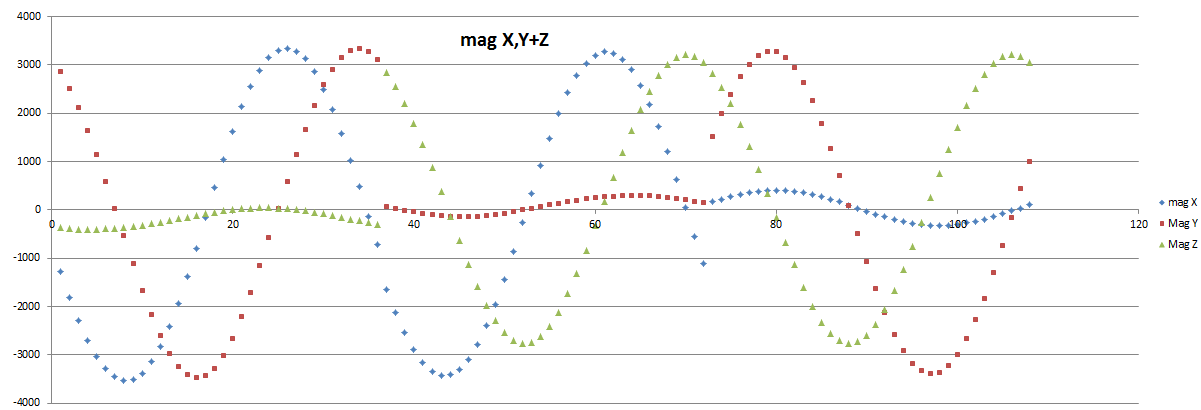
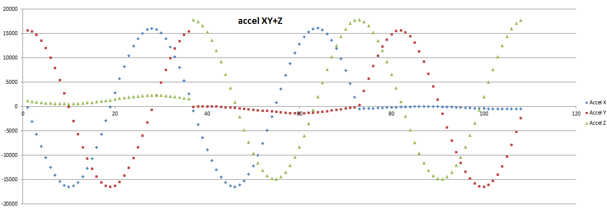
 * It gathers both Magnetometer and Accelerometer data to be  
 * subsequently inputted to Magneto software, which produces values 
 * to be incorporated as adjustments in the use of the LSM303D.
 * 
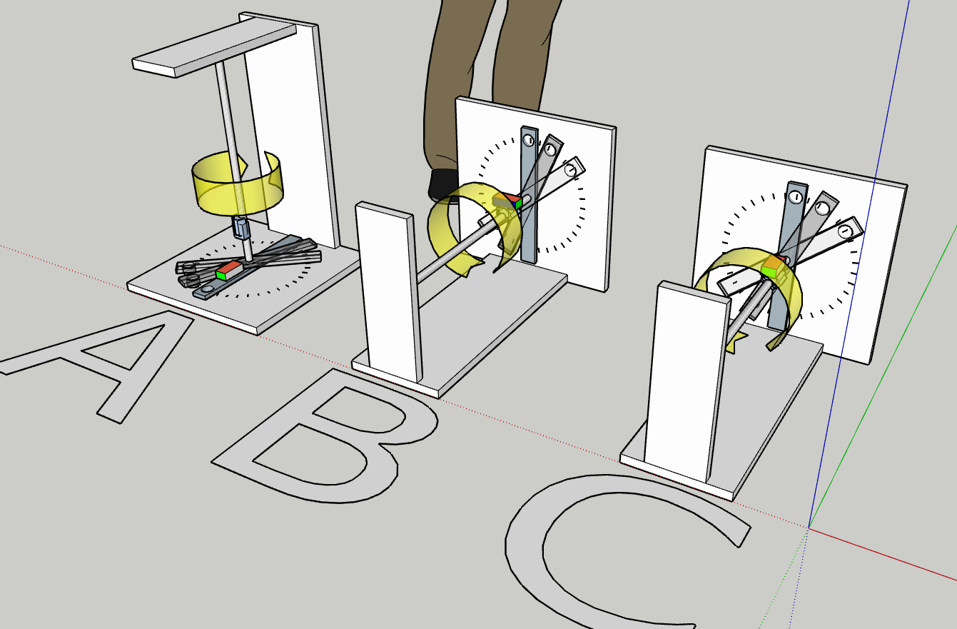
 * The LSM303D will need to be in a magnetic-free environment
 * (use wood, stainless steel, pvc etc) and be able to 
 * accurately position in rotation of 24-36 equal STATIONARY 
 * measurements around a full circle.
 * 
 * Each stationary position gathers multiple reads and averages 
 * the results prior to outputting the value for that position
 * 
 * This sketch (and the associated horizontal incremental rotation)
 * needs to be run six times: with the LS303D 
 * positioned in each of all possible 6 orientations for each run.
 * it will produce one line of space-separated data each 
 * stationary 'read' position:

 * This sketch uses SerialPrint to output the values. To capture the 
 * outputs, simply use the serial monitor. When complete select copy 
 * and paste from the serial monitor and paste to excel. From excel 
 * change data/text-to-columns, use space separated values then 
 * save out as tab delimited.txt file fromat the save-as menu. 
 * 
 * This is so the resulting .txt file can be opened by Magneto
 * 
 */
#include <Wire.h>
#include <LSM303.h>
LSM303 compass;
int numReads = 100; // how many samples in each stationary location
int magScale = 1;
int accelScale = 1;
int i = 0;


void setup()
{
Serial.begin(9600);
Wire.begin();
compass.init();
compass.enableDefault();
Serial.println("Multi-Sampling starting soon....)"); 
delay (2000);
}


void loop()
{
Serial.print("Move_it_now!"); delay (5000);
Serial.print("get_ready..");  delay (800);
Serial.print("3.."); delay (1000);
Serial.print("2.."); delay (1000);
Serial.print("1.."); delay (1000);
Serial.print("sampling...");

float Xa, Ya, Za, Xm, Ym, Zm;
for (i = 0; i < numReads ; i++){
  compass.read();
  
  Xa += compass.a.x/accelScale;
  Ya += compass.a.y/accelScale;
  Za += compass.a.z/accelScale;

  Xm += compass.m.x/magScale;
  Ym += compass.m.y/magScale;
  Zm += compass.m.z/magScale;
  delay (150);

}

Serial.print("Output(Mag_then_Accel): ");
//print mag
Serial.print(Xm/numReads); Serial.print(" "); 
Serial.print(Ym/numReads); Serial.print(" "); 
Serial.print(Zm/numReads); Serial.print(" ");
//then accel
Serial.print(Xa/numReads); Serial.print(" "); 
Serial.print(Ya/numReads); Serial.print(" "); 
Serial.println(Za/numReads); 


delay (1000);


}

sixd, your data is not correct l believe, attached is my raw data, mag 2 gauss, accel 2g. sheet 1 my raw, sheeet 2 yurs, sheet 3 my magneto corrected.
My imu has same LSM303 compass just l have the gyro.
look at my data and see the difference. But in saying that my compass still has lots of tilt error.
mag accel raw in shed APJ code.xlsx (62.8 KB)

sixD, l tried your code and working correctly (you could cut your sampling back to a max 64 as per Merlin, or way less to get the results working correctly to start with. I just took 1 lot of data on a stationary IMU.
Have a look at my data then yours, your # don’t seem right.
Take some photos of how you have the IMU or describe it, as it doesn’t look like you have the IMU axis parallel with a horizontal axle like my photo and rotating the imu/horizontal axle thru 360 .

thanks for sticking with this @kevin1961. appreciated. (i hope you got some time to go to the wooden boat festival?)

yep, I agree i will cut the sampling # back until i get some progress. But when you say [quote=“kevin1961, post:63, topic:11611”]
I just took 1 lot of data on a stationary IMU
[/quote] do you mean only one rotation with the board in only ONE of the six positions?

YOUR FILE:
Thanks for sending your data file. I agree the numbers seem very different. sure there is going to be some device + locational difference, but maybe not that much?

specifically: i wonder why ALL of your your accelerometer values vary on each new data-line. if the board is flat (say Z axis is up) then as it rotates around the flat 360, then shouldn’t Z stay the same for each of those readings, and only X and Y vary??? Z will only change for a different board orientation (i.e. the NEXT one of the six) etc?

Do you think the numbers could mean a faulty LSM303D board? hmmmm, i wonder if there is a board reset?

OK I will send photos separately. The board definitely looks flat, maybe a rounding error off from perfect, but flat.

sixD, you should only be doing 3 postions axis, x,y,z.
I only took 1 measurement just to see what data you were collecting and it was the same data reading when l took 1 measurement with my code (no rotating, IMU sitting on bench)

If you look at my photo the Z axis is parallel with the axle (Z axis goes thru the IMU, X axis vertical) and you rotate 360 NOT ON THE FLAT.
How can you have a horizontal axle and turn it, with the IMU taped to it, it is rotating with the axle, not on a flat 360.
But l have just done compass rose (on the flat 360 turn) Raw Mag X, Y data and Magneto corrected Mag,X,Y from axle rotation and it isn’t correct.
If l use the compass rose Raw into magneto and use that correction it is a centred circle.
Even then it still has major tilt error

This comes as a surprise to me.

I thought that: Xup, Xdown, Yup, Ydown and Zup, Zdown meant 6 ‘lots’ of data. The XY and Z are clearly printed on the board:

HERE ARE IMAGES OF CALIBRATION RIG
LSM303D is in the middle very near the middle of the big wooden pivoting ‘arm’, pivots on a clear acetate sheet over a printed compass rose glued to plywood on a stainless steel table.
In this pic. it just so HAPPENS to be on the ‘flat’ i.e. X and Y out horizontally and Zup.

The rig allows accurate flat (horizontal) rotation with no other rotation:

SO I AM CLEAR
Your last posting means that i am going to need some description of what you say: [quote=“kevin1961, post:65, topic:11611”]
you should only be doing 3 postions axis, x,y,z.
[/quote]

Here are the conventional labels for the “6 degrees of freedom” (the only one that i also use is ‘heading’ = yaw):

But when we say ‘rotate’, it may not be clear which we mean, so to clear that up here are conventional labels for referring to WHICH rotation we mean:

Can you please let me know each of:

  1. which three LSM303D orientations do you mean? (eg is X up the ‘same’ as X down etc), and
  2. which rotation. (eg turn about thetaZ, thetaY, thetaX)?

I have been fixing the LSM303D in all 6 directions and then rotating (10 degree increments) around 360 degrees of thetaZ

OMG, I think we might just be getting somewhere…

thanks in anticipation!

sixD, you need to have another look and and open your eyes, does mine look anything like yours, l am rotating the axle l am not turning the bucket, my segment device is on the end of the axle and l turn the axle.
Have another read of my posts, l never say turn the IMU l say rotate it.
You just need to do x,y,z axis once, not in both directions as when it is ROTATED about THE AXIS it goes max ±.
As per your drawing of axis and arrows, please explain how turning your device rotates the axis? you are just pointing x,y,z in a different direction around 360 degrees on the flat.
REPEAT have a look at my photo, l am NOT turning the bucket, l am rotating the axle.
Now l reckon the penny might have dropped. I hoping anyway!

The difference between “turn” and “rotate” may be crystal clear to you, but that doesnt mean others will always know what you mean.

Your language in your recent post @kevin1961 is not respectful - i have been nothing but polite with you, and i would hope that you could extend the same courtesy to me.

I suggest you re read Merlin’s posts, he shows how it is to be rotated at the top of the page, best of luck.
kevin1961 out

I have gone back to first principles and re-read all information here and in the links, but i am still finding the LSM303D uncalibrate-able!!

i even closed off the possibility that my unit was faulty and wired in a new unit, but same outcome :frowning: There must be something that i am overlooking, but for the life of me i cant see what it is. PLEASE SEND HELP!.. i just want a tilt-compensated compass.

The problem (as with each run earlier in this thread) is that when the heading is constant but the unit tilts or rolls the heading does not remain constant.

Here is my process:

  1. Gather up the RAW data from the LSM303D’s Magnetometer and Accelerometer by rotating the unit in equal increments around each axis
  2. Put data into Magneto software to get the Mag & Accel compensation factors
  3. Insert the compensation factors into heading.ino (being very careful about the + & - signs)
  4. Test

OK can you see any problems with this process??


Firstly GATHER THE RAW DATA:

There are three data gathering runs (see pic.):
A: is with the unit on the flat. (this is for heading) and rotated about a vertical axis
B: the unit is horizontal and rotated incrementally around a horizontal axis
C: the unit is horizontal but with a different face parallel to the axis and also rotated around the horizontal axis.

For each of A,B and C

  • my increments are 10 degrees each, so that’s 36 stationary points around a circle.
  • at each reading i average 50 readings back to one data output for that position - the code for this is earlier in this thread.
  • this gives 108 orientations for Mag & Accel affected ONLY by gravity (they are stationary data reads)

For completeness here i can graph the RAW data (all 108 rows of x,y and z outputs, to see if the outputs are something that kinda ‘looks right’.

Here is MagRAWdata for x-y, then y-z then x-z:

…and here is AccelRAWdata for x-y, then y-z then x-z:

For one extra check:

i can graph ONLY the relevant parts of each of the 108 data rows [i.e. only the 36 ‘A’-orientation points for x-y, only the 36 ‘B’-orientation for y-z, and only the 36 ‘C’ orientation for X-Z] then this is the graphed output:

for mag:

and then for Accel:

Magneto can make the ovals into circles and centre the data and as you can see every one of the charts are like this EXCEPT FOR accel x-y which is weird! could this be where the problem lies?

THEN PUT THE DATA INTO MAGNETO

i separate the output into two tab-delimited .txt files, one Mag and one for Accel. I assume that i do this for all 108 points, not just the 36 for each orientation??

Can anyone kindly clarify if the process this far is correct?

many thanks

dB

Unless there is an error in the code or the mounting arrangement (with a nearby bit of iron or magnet), the “accel x-y” plot suggests that the sensor is defective. It should look similar to the other two accel plots.

Magneto fits an ellipsoid, not ellipses, and can use all the data points you provide. The more points, and the more evenly they are spaced over the 3D orientation sphere, the better.

It is in fact undesirable to consider only certain orientations of the sensor.

sixD, I don’t know a lot about this method of calibration, but I don’t think your accelerometer is defective. From looking at your test setup and your graphs, it doesn’t look like you ever subject both the X and Y axes (blue and green) to gravitational acceleration at the same time. That is why you only see a cross pattern on your accel X-Y graph, and I think it explains why the software is having such a hard time “circularizing” it.

You should be able to get better data by adding another run (i.e. take your “A” setup and tip it over so the axis is parallel to the ground), but I think Jim is right that you want to get readings in as many orientations as you can; it might actually be better to wave the sensor around freely than to try to constrain its rotation to certain axes.

Kevin

Hi SixD, good to see you finally worked out the difference between turning and rotation of the axis.

Hi Kevin, l would thinking waving the IMU around for Cal won’t work for the Accel as it would have a acceleration component as well as gravity??
Merlin states that you only need to do approx 24 steps i.e 15 degree increments for Magneto to give a good enough correction ratio.
My previously attached photo shows a V3 in the position you indicated for the X,Y axis data to be taken.
That all being said, after magneto correction to Mag and accel, instead of max/min correction, my tilt error decreased from 13 degree to 11 degree error at 45 degree tilt. So not worth the effort. Better off building a gimbal and decreasing error to <2 at 45 degrees(when you are not constrained by size).
What l can’t understand is the Accel gives accurate degrees of tilt, which l would have though meant the complete DCM formula would give just as accurate tilt compensated heading, which it doesn’t.

Hi.
thankyou @Jim_Remington thats i i first thought it was a defective unit too, but thinking a bit more on it, and as per @kevin…[quote=“kevin, post:72, topic:11611”]
but I don’t think your accelerometer is defective
[/quote] as he says:

REASON: the X and Y are producing reasonable results in other orientations, so they must be working. BUT it’s def-o a problem and needs to be fixed. maybe i’m missing one orientation in my calibration.

re calibrate ‘loose’ or on the rig:
@kevin, regarding waving the IMU instead, i’ll keep it in mind, but from my testing i’d say that i agree with @kevin1961 that it would introduce more problems than it’s worth.

##new check
so instead of plotting values against each other, i plotted my previous data against their dataNumber (for 1 thru 108 data points) and got this:

For MAG:

and for ACCEL:

so, while i thought i had them all covered, the first third (being 1-36) is flat-as-a-pancake so this data says that i am missing one IMU orientation. riiight.

##adding the missing orientation:
so i took away the flat heading rotation that i called “A” above (rotated around a vertical axis) and substituted the data from the missing IMU position for one another rotation (around a horizontal axis)

and the new data now looks like this

for MAG:

and for ACCEL:

hurrah, this looks to me like i think the RAW data should. hopefully you guys agree?

rerunning thru magneto:

so i re-run all 108 data points thru magneto and it produces different calibrations values, but not very different. i input them into heading, carfully checking the +,- signs.
OUTCOME: unfortunately the heading output is still NOT tilt-compensated :frowning:

WHERE TO NOW?: this is some progress, no doubt, but i’m still not in the land of a tilt-compensated-compass. my current hunch is that the Xs and Ys should be reversed somehow. (i think this was true of early versions of LSM303 c/w later versions??. @kevin can you shed light on this?) its the only way i can see how a roll or pitch can make heading so much WORSE.

any other things to try would be gratefully received!

thanks

sixD

Hey SixD

I was having trouble with tilt compensation of my LSM303DLHC compass for an astronomy use.

For now I’ve managed a workaround involving limiting the position of the sensor, but I’m interested in figuring out the whole thing.

One quick question:

is this the code you are using for calculating the heading:?
https://forum.arduino.cc/index.php?topic=265541.0

fXm_comp = fXmcos(pitch)+fZmsin(pitch);
fYm_comp = fXmsin(roll)sin(pitch)+fYmcos(roll)-fZmsin(roll)*cos(pitch);

I’ve noticed in your graphs that you calculate pitch and roll, which tells me you are using these formulas (which involve lots of trigonometric functions like sin and cos).

There is another way to calculate the heading, using vector math (dot products and cross products). that’s the one I’m using, the bases is contained in the Pololu LSM303 library, ¿have you checked that out?

Hey @Adun,

yep, thats the one! A number of the tilt-compensated heading calcs i’ve seen use those formulae.

I would add this though: One of the three LSM303 library files is called heading.ino (i’ve taken out the remarks to keep it short):

#include <Wire.h>
#include <LSM303.h>

LSM303 compass;

void setup() {
  Serial.begin(9600);
  Wire.begin();
  compass.init();
  compass.enableDefault();
  
  compass.m_min = (LSM303::vector<int16_t>){-32767, -32767, -32767};
  compass.m_max = (LSM303::vector<int16_t>){+32767, +32767, +32767};
}

void loop() {
  compass.read();
  

  float heading = compass.heading();
  
  Serial.println(heading);
  delay(100);
} 

yup, it doesn’t get much simpler than that. in this trouble-shooting saga, i compared the heading output from the above sketch to the heading that outputs from the equation(s) approach (the ones you mention) and they come out exactly the same. i guess the same equations are onboard the IMU too. Anyway that was a) nice to know b) not helpful for solving any part of my problem.

i’m glad you are also [quote=“Adun, post:76, topic:11611”]
interested in figuring out the whole thing.
[/quote]

…after all this time all i can add is me too!

can you tell me more about the [quote=“Adun, post:76, topic:11611”]
another way to calculate the heading, using vector math (dot products and cross products). that’s the one I’m using, the bases is contained in the Pololu LSM303 library,
[/quote]

either my library isnt uptodate or i’m missing something!

thanks much

sixD

Hi

I extended the class from LSM303.h file, which contains the body of the heading() method.

The template for the heading() method expects a “from” vector (which should be of magnitude 1 or -1), and it returns a heading relative to it.

The library always uses [0, -1, 0] which is the Y axis of the sensor for this, but as the sensor aims higher near zenith, it’s heading makes no sense. Above 45° you should use the X axis (and add 90° to the result). This requires modifying (or extending) the Pololu library.

Try this experiment: Modify the library to calculate heading using 3 different “from” vectors: X (-1,0,0) Y(0, -1,0) Z(0,0,1), and then plot the data, like you’ve done (tilting from zero to zenith). You will see what I mean.

My workaround was to switch to using the Z axis (0,0,-1) and use the sensor inclined, so that Z should is always be horizontal and give a good reading, it works for me because it’s for a telescope (not a boat) and it can keep the sensor vertical (zero rolling)

G’day,

i understand and as you say @Adun it makes perfect sense for a telescope. and if i needed such a big range i think what you’re suggesting would be perfect. if that happened on a boat, the mast is in the water.:worried:

in regular use for a boat the tilt (roll) would go around 45 degrees but rarely and only momentarily and pitch would only be +/-10 ish i’d guess

the .h file

Hats off to you, sir for getting into the .h file. something i’ve never done. I’m interested, though that you say… [quote=“Adun, post:78, topic:11611”]
The library always uses [0, -1, 0] which is the Y axis of the sensor for this,
[/quote]

…and i’m wondering if that is a clue to part of my problem/situation.

see, with the board ‘on the flat’ it’s the Z axis which is up/down so heading would be based on X and Y axes, right? i wonder why the library would default to Y?? does that mean all this time that i should have my board on its ‘edge’ as its starting orientation, rather than on-the flat??

plus it might explain why the outputs for pitch and roll have always seemed so accurate compared with the wild errors that get introduced into the heading output - something i have always wondered how 2 outputs can be so reliable, but the third is lousy.

##one other thing

i have noticed that the tilt compensation amount varies around the heading. for example if the heading - that’s the red line below - is at 100 (east-ish) and held constant and then the pitch goes up say 20deg - the first blue peak - then heading will wrongly adjust by MINUS 60degrees -thats the first red ‘dip’.


but if heading is 270 (west) and held constant and then the pitch goes up by the same 20deg - the second blue peak -
then the heading will wrongly adjust by PLUS 60deg that’s the red ‘bump’.

Your experiment

I’m happy to try ANY experiment, but have never dived into the .h file. can you kindly post some code of what you are suggesting?

or maybe the above gives you some clue as to what’s going on?!?!?

thanks much

sixD

Come On Jim, how about posting your complete code that can deliver what l would call amazing results that you have been able to get out of IMU’s.
I ask, because Kris has his code used by possible the biggest supplier of product at our level, has it openly available to all and l have found even his can’t, down where l live, come anywhere near the the level of accuracy that you say you can get.
Com on supply your code please.
Thanks Kevin