LSM303D tilt compensation problem

compass.m.x and compass.m.y are the values of interest, if you have the Z axis vertical.

Use the serial output to print those while slowly turning in a full circle, and plot them using a spreadsheet or other program.

The actual values output are proportional to the magnetic field component along each axis, and will depend on the sensitivity of the particular magnetometer.

Overview of compass calibration: https://edwardmallon.wordpress.com/2015/05/22/calibrating-any-compass-or-accelerometer-for-arduino/

OK @Jim_Remington good idea. here are the results of the slow full circle:

that is a LONG way off a circle, eh? So we are getting some progress.

But what now?

Well, that is the problem, and fortunately it is “easily correctable”.

You need to correct the relative X and Y gains and offsets to turn that ellipse into a circle, centered on the origin.

If you want to post the data, I could use the technique described in my Sparkfun forum post to calculate the correction factor. However, that particular correction would only be accurate for the horizontal plane, with Z down.

You really need to do the full 3D magnetometer correction described on these pages: http://sailboatinstruments.blogspot.com/2011/08/improved-magnetometer-calibration.html

That will involve collecting a full 3D dataset and presenting it to the Magneto program.

thanks @Jim_Remington, you just became my personal hero. It is appropriate you pointed me to “sailboat instruments” blog, because i am making my project is for sailing too :slight_smile:

I will download that software and post back here with progress when done. Thanks again!

MagCal software installed. I’m unsure which value to use for the Norm of the Earth Magnetic Field (Hm)

The help text says you can get the data (their link is a 404) but i found it here: NCEI Geomagnetic Calculators

But none of the outputs are a “Norm”… instead it produces 8 fields:

Is one of these values a "norm of the Earth Mag field?"

thx

It doesn’t matter what the value is, unless you are interested in actually measuring the strength of the Earth’s magnetic field.

Just pick a value that is roughly the average of all the measurements and you won’t lose precision. Looking at your plot, 1000 would be a fine choice.

SixD, if you go back to the Pololu site were you got the AHRS from there is another program there called Pololu Open IMU, which uses Merlins approach ( but is using Mag/Accel/Gyru, Gyro will give you ROT, rate of turn in degrees per second, which is a big advantage with a AP), unfortunately when l have tried using it the tilt compensation is great for a few seconds then the heading (compass reading ) it just drifts rapidly.
Myself and Jack Edwards have tried and tested Merlins coding without success, as l stated at the start about SailBoatInstruments he has done the coding to rectify deviation of compass headings (works beautifully as long as your compass is repeatable on each restart, which you may find it isn’t. Turn yours on/off a few times and see what happens to the heading, moving the IMU when off) but the tilt correction code reduced my tilt error by a couple of degrees, i.e ± 12 at worst to ± 10, so will love to here you are able to clear your up.
Were do you live (what degree of Mag field tilt do you have). Are you only after a compass heading from a tilt compensated IMU or are you going to use this as an input into something?
That X,Y plot you showed, was that Raw data, or after the Mag Cal correction? I imagine raw as it wasn’t centred, by plotting the X,Y after the correction you can confirm it is working correctly.
The AHRS does what it can which is centres the ellipsoid and averages the max/min but it doesn’t make the ellipsoid into a circle and it is only doing it on the level, not as Jim rightly says in 3D, i.e when you wave it around.

thanks @kevin1961. There are a few things in your post

  1. [quote=“kevin1961, post:27, topic:11611”]
    Go back to …Pololu Open IMU, which uses Merlins approach
    [/quote] …but then you go on to say “without success”!

  2. [quote=“kevin1961, post:27, topic:11611”]
    SailBoatInstruments … to rectify deviation. works beautifully as long as your compass is repeatable on each restart, which you may find it isn’t
    [/quote] …hmmm . i have assumed it was the same each time up until now but i can see I will have to test that.

3.[quote=“kevin1961, post:27, topic:11611”]
Were do you live?
[/quote]: in sunny Sydney

  1. .[quote=“kevin1961, post:27, topic:11611”]
    Are you only after a compass heading from a tilt compensated IMU or are you going to use this as an input into something?
    [/quote]: … as an input to a real time sailing VMG product + course suggester. i wanted a tilt-compensated compass as a 1st step to this… What a problematic 1st step its been !

5.[quote=“kevin1961, post:27, topic:11611”]
That X,Y plot you showed
[/quote] Yes it was raw data

6.[quote=“kevin1961, post:27, topic:11611”]
The AHRS does what it can … but it doesn’t make the ellipsoid into a circle … not as Jim rightly says in 3D
[/quote] I thought thats why MagCal has X,Y and Z columns. Have i got that wrong? I need to be able to “wave it around” and be a tilt-compensated compass!

Lastly i have found EITHER MagCal or Magneto. Both seem to do a very similar thing. But critically the ONLY place i have managed to find the equations with what to do with the corrections is at Tutorial: How to calibrate a compass (and accelerometer) with Arduino | Underwater Arduino Data Loggers in a .jpg (so i cant even copy the text!) repeated here for simplicity:


Does anyone have / point me to a script for it?

I am in the process right now of working out how to make the tab-delimited text file from the arduino data.:stuck_out_tongue:

I hope this post is/will be useful for others wanting a tilt-compensated compass! We are getting there…Phew!

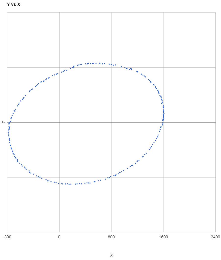
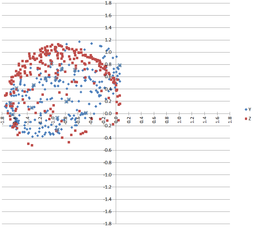
sixD,The AHRS as is, doesn’t do 3D correction, adding Merlins code and Mag Cal correction data supposedly (before anyone jumps on me) makes the ellipsoid a circle and centres it in the 3 planes, BUT l haven’t found this to be the case. I asked Merlin to confirm if the coding in that example on the under water blog was correct but he never answered. My Guru, Jack Edwards has gone through and checked the way l was implementing the correction formula and it is correct in the example given. But we both found that it doesn’t make the compass heading as tilt compensated as we all hoped and there is no use in using it.
Much later l found Merlins coding correction l was after all along was already on Pololu web site (ironicly, no one new that’s what it did) as the Pololu Open IMU, but as l say (please test it) it drifts rapidly and Mike Baker hasn’t answered a question re this(l have tried changing everything l could in the code without success).
I was after a < ± 2 dynamic accuracy to bring it inline with the bought sensors. I believe the only way to get this is with a gimbal, in Sydney you don’t have as bad mag field tilt as down here and hence you will get better results than l. I am pessimistic of how well the commercial units work and would love to have one and thought l would have to pay the $A700-1200(l did buy one, see later comment) to get the accuracy l thought l needed, but V3 and gimbal is giving me the accuracy l am after. But a Auto Pilot heading sensor (which is what l am after) just really needs to be accurate, in a worst case, swinging ± 30 from a set heading with as little tilt error, as in rough water the boat is jumping around a lot anyway.
If l was after the best heading sensor without paying the big bucks, l believe you won’t get a better unit than the one from Kris l posted.
I bought a commercial unit from a AP builder/supplier that they said would be <± 1, when l tested it, it was ±8 (this was static testing let alone dynamic). They then retested there units with the same result. The R+D manger is not the manager anymore. They gave me a refund. Hence my pessimism about commercial units accuracy.
So what sort of accuracy are you after, the gyro is what gives a stable heading but if it is turning when you start the IMU it computes the ROT into the start cal and then the heading can be off, right from the start. Your unit doesn’t have that but it won’t be as good a heading, when you add velocity into the equation, then they use the gyro as the main input and the accel and mag as corrections to the gyro.

It is a interesting subject that l have researched now for 18 months, l might have basic coding skills but have looked into a lot about IMU’s, and you get what you pay for, $35 chip against $1200 like Airmar H2183 which all others are graded against.
The issue with Merlins approach is that you are correcting the Mag and you need to do the same for the accel (which l did) but the chip is the inaccurate part, you can cal it all you like, but it has inbuilt inaccuracy hence why if you want accuracy you have to buy a better quality chip like military grade that you can’t get anyway at $50K
http://www.vectornav.com/support/library/imu-and-ins have a read re accuracy and you see what we are up against.

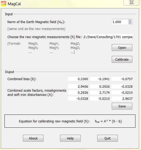
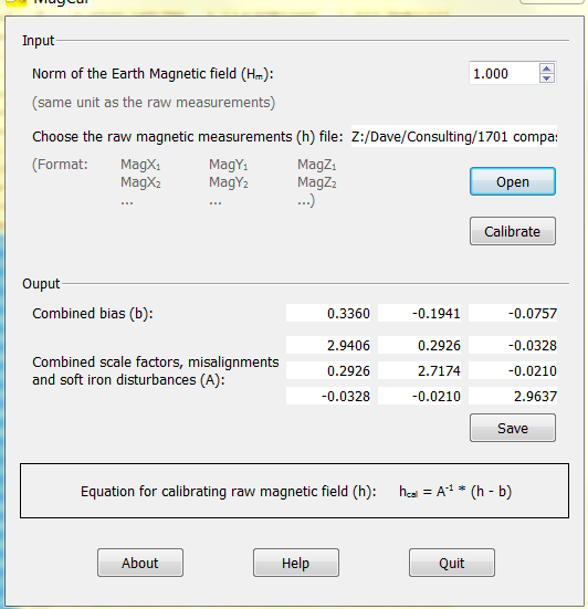
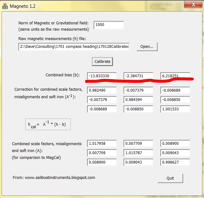
Below is an example of the code you are after (change all variables to your Magneto data). The screen print you have uploaded is the correct way to implement Merlins corrections (also look at Pololu Open IMU)

#include <Wire.h>
#include <LSM303.h>

LSM303 compass;

const float alpha = 0.15;//default 0.15, higher number less filtering=faster response
float fXa = 0;
float fYa = 0;
float fZa = 0;
float fXm = 0;
float fYm = 0;
float fZm = 0;

void setup() {
Serial.begin(9600);
Wire.begin();
compass.init();
compass.enableDefault();
}

void loop()
{
compass.read();
float pitch, pitch_print, roll, roll_print, Heading, Xa_off, Ya_off, Za_off, Xa_cal, Ya_cal, Za_cal, Xm_off, Ym_off, Zm_off, Xm_cal, Ym_cal, Zm_cal, fXm_comp, fYm_comp;

// Accelerometer calibration
//AP/all data/data on trip/16166
Xa_off = compass.a.x + 295;//pitch
Ya_off = compass.a.y + 287;//roll
Za_off = compass.a.z - 717;
Xa_cal = 1.001328Xa_off + 0.000286Ya_off + 0.002095 Za_off;
Ya_cal = 0.000286
Xa_off + 0.984450Ya_off + 0.000302Za_off;
Za_cal = 0.002095Xa_off + 0.000302Ya_off + 0.985394*Za_off;

//Xa_off = Xa_off0.33;
//Ya_off = Ya_off
0.33;
//Za_off = Za_off0.33;
// Magnetometer calibration
//bris river magneto , 3205
Xm_off = compass.m.x + 216;// correct should be default(- bias)= - (bias) -216 = +216 // magneto b = -216 //(100000.0/1600.0) - 8397.862881;
Ym_off = compass.m.y + 208; //(100000.0/1600.0) - 3307.507492;
Zm_off = compass.m.z - 334; //(100000.0/1600.0 ) + 2718.831179;
Xm_cal = 1.046360
Xm_off + 0.078575Ym_off + -0.027728Zm_off;
Ym_cal = 0.078575Xm_off + 1.080417Ym_off + -0.005989Zm_off;
Zm_cal = -0.027728
Xm_off + -0.005989Ym_off + 1.108273Zm_off;
// scale mag axis
//Xm_cal = Xm_cal1.45;
//Ym_cal = Ym_cal
1.3;
//Zm_cal = Zm_cal*0.5;
// Low-Pass filter accelerometer
fXa = Xa_cal * alpha + (fXa * (1.0 - alpha));
fYa = Ya_cal * alpha + (fYa * (1.0 - alpha));
fZa = Za_cal * alpha + (fZa * (1.0 - alpha));

// Low-Pass filter magnetometer
fXm = Xm_cal * alpha + (fXm * (1.0 - alpha));
fYm = Ym_cal * alpha + (fYm * (1.0 - alpha));
fZm = Zm_cal * alpha + (fZm * (1.0 - alpha));

// Pitch and roll
roll = atan2(fYa, sqrt(fXafXa + fZafZa));
pitch = atan2(fXa, sqrt(fYafYa + fZafZa));
roll_print = roll180.0/M_PI;
pitch_print = pitch
180.0/M_PI;

// Tilt compensated magnetic sensor measurements
fXm_comp = fXmcos(pitch)+fZmsin(pitch);
fYm_comp = fXmsin(roll)sin(pitch)+fYmcos(roll)-fZmsin(roll)*cos(pitch);

// Arctangent of y/x
Heading = (atan2(fYm_comp,fXm_comp)*180.0)/M_PI;
if (Heading < 0)
Heading += 360;
//Serial.print(“Xa_off”); Serial.print(Xa_off); Serial.print(" “);
//Serial.print(“Ya_off”); Serial.print(Ya_off); Serial.print(” “);
//Serial.print(“Za_off”); Serial.print(Za_off); Serial.print(” ");
//Serial.print("compass aX “); Serial.print(compass.a.x); Serial.print(” ");
//Serial.print("compass aY “); Serial.print(compass.a.y); Serial.print(” ");
//Serial.print("compass aZ “); Serial.print(compass.a.z); Serial.print(” ");
//Serial.print("Xa_cal “); Serial.print(Xa_cal); Serial.print(” ");
//Serial.print("Ya_cal “); Serial.print(Ya_cal); Serial.print(” ");
//Serial.print("Za_cal “); Serial.print(Za_cal); Serial.println(” ");

//Serial.print(“Xm_off”); Serial.print(Xm_off); Serial.print(" “);
//Serial.print(“Ym_off”); Serial.print(Ym_off); Serial.print(” “);
//Serial.print(“Zm_off”); Serial.print(Zm_off); Serial.print(” ");
//Serial.print("compass mX “); Serial.print(compass.m.x); Serial.print(” ");
//Serial.print("compass mY “); Serial.print(compass.m.y); Serial.print(” ");
//Serial.print("compass mZ “); Serial.print(compass.m.z); Serial.print(” ");
//Serial.print("Xm_cal “); Serial.print(Xm_cal); Serial.print(” ");
//Serial.print("Ym_cal “); Serial.print(Ym_cal); Serial.print(” ");
//Serial.print("Zm_cal “); Serial.print(Zm_cal); Serial.println(” ");
Serial.print("Pitch (X): “); Serial.print(pitch_print,0); Serial.print(” ");
Serial.print("Roll (Y): “); Serial.print(roll_print,0); Serial.print(” ");
Serial.print("Heading: "); Serial.println(Heading,1);
delay(100);//default 250

I’ve implemented the Magneto correction in my version of a tilt compensation program, and it works very well.

It is EXTREMELY important that you verify the correction as implemented in your code. That can only be done by outputting the corrected 3D magnetometer values in the same way as you first output the raw 3D magnetometer values, and run Magneto again.

The resulting correction matrix should have 1.0 for the three diagonal matrix elements and 0.0 everywhere else, and 0.0 for the three offsets. If so you have implemented the correction correctly, and tilt compensation will work properly.

Keep in mind that after mounting the sensor in a new environment, you may need to do a new calibration run.

Hi Jim, how much did the accuracy re tilt heading did you see as an improvement?

Jim, your testing corrected data scenario, reminded me that that was what my problem about the implementation of the correction was.
I didn’t get the results l should have and when l asked about this to Merlin he never answered and l was unsure if the correction implementation was correct. Which l believe it was but couldn’t get the 1+0’s, so l may be
being premature about possible results and are hoping it still maybe able to correct the tilt inaccuracy.
Regards Kevin

Jim, is the above code correct implementation and if not, would you post yours?

Run the test I suggested and see.

UPDATE: working with the useful guide previously referred to (at LSM303DLHC - Calibration, Pitch, Roll and Tilt Compensated Heading - Sensors - Arduino Forum) and using the MagCal software because i had it already (i.e. not Magneto) my raw data AFTER scaling dividing all by 1,000,000 then ‘calculating’ gets these values:

which i input into the second script, HOWEVER i need guidance on factoring in the scaling of the raw input into this script. my logic is that this would ALSO have to be divided by the same scale, so i have:

Xm_off = compass.m.x*(1/11000.0) - 0.3360;
Ym_off = compass.m.y*(1/11000.0) + 0.1941;
Zm_off = compass.m.z*(1/9800.0 ) + 0.0757;

EXPLANATION: i get the 1/11000.0 from the (100000.0/1100.0 from the supplied script) and divide this, THEIR scale by MY scale which was 1000000 Does that make sense? Is this right?

ANYWAY so then i upload the new sketch with these values (and scaling) and grab another bucket of values pointing the sensor ‘painting the inside of a sphere’ a second time. The above website says running it a second time (as i check, i guess) you should “see the values are all closer to almost zero” and that’s not wot i get! Heres mine:


so thinking that graphing this ‘calibrated’ data might reveal some insight???

Clearly not circular, clearly not centred on zero. What are your thoughts?
thx!

EXTRA REGARDING SCALING THE RAW STUFF: from the @edwardmallon wordpress site he states If your sensors have SPI or I2C outputs, they will usually directly produce the required format. For example, the MicroMag3 magnetometer directly produces counts from -3411 to +3411.

OK. but my LSM303D outputs values from approx: +280,000.0 to -280,000. So instead of diving by 1M which is what is in the above example, maybe 100 would have been fine? bottom line is MagCal values are VERY different from his example…

MagCal outputs the INVERSE of the matrix that you need to use for the correction.

That is why I don’t use it, and use Magneto instead.

For the norm of the magnetic field, again, I recommend to use a value that is roughly the average absolute value of all the measurements.

ok i dont understand wot you mean by inverse of the matrix @Jim_Remington (note: i thought sailboatinstruments blog said both app.s were pretty much exactly the same but just used different equations to get their output?) but ANYWAY i will download and use Magneto instead to avoid complication + irritation.

oh, and do the same SCALING issues apply to Magneto regarding the scaling of the raw output too?

i will do this tomorrow. standby…

You could look up “matrix inverse”, but here it is:

very kind @Jim_Remington, thanks

Here is the re-run with scales of
x: 1000/1100
y: 1000/1100
z: 1000/980

AND magneto used instead of MagCal (no inversion needed:) Based on the raw data:

re-run with new new data:

values (underlined in red) ARE much clsoer to zero! HURRAH.

Now to calibrate the accelerometer too… standby