I have a DRV8838 in usage that is supposed to trigger a solenoid. The logic circuit is powered with 3.3V and controlled by an ESP32 which all works fine (i can see voltage raise and fall for PHASE and ENABLE pin as the ESP32 triggers HIGH and LOW)
The motor circuit is powered with 9V (originating from an S10V3F9) and i can measure that voltage alright at the VM pin. But Vout1 and Vout2 only give me stable 3.05V (i can see that also they drop to 0V if the ESP32 triggers the ENABLE PIN)
If i replace the DRV8838 with a second one i have it gives me 0V for Vout1 and Vout2.
What could the source for that problem (not getting expected 9V)? (i did not really pay attention in school when it came to theory of electricity so i am wandering in the dark here)
Hello.
Can you post some pictures of your setup as well as information about your solenoid and power supply? Also, can you measure the output of your power supply and regulator to confirm that they are working and that the voltage is not dropping when the solenoid is activated? If it does drop, that could indicate your circuit isn’t able to supply enough current for the solenoid.
- Patrick
This is the schematic from which i built. Though i replaced the ESP-07 with an ESP32 and did not wire in the debug part to the left of the ESP-07
Gardena1251-Controller-H-Bridge-Schematic.pdf (103.8 KB)
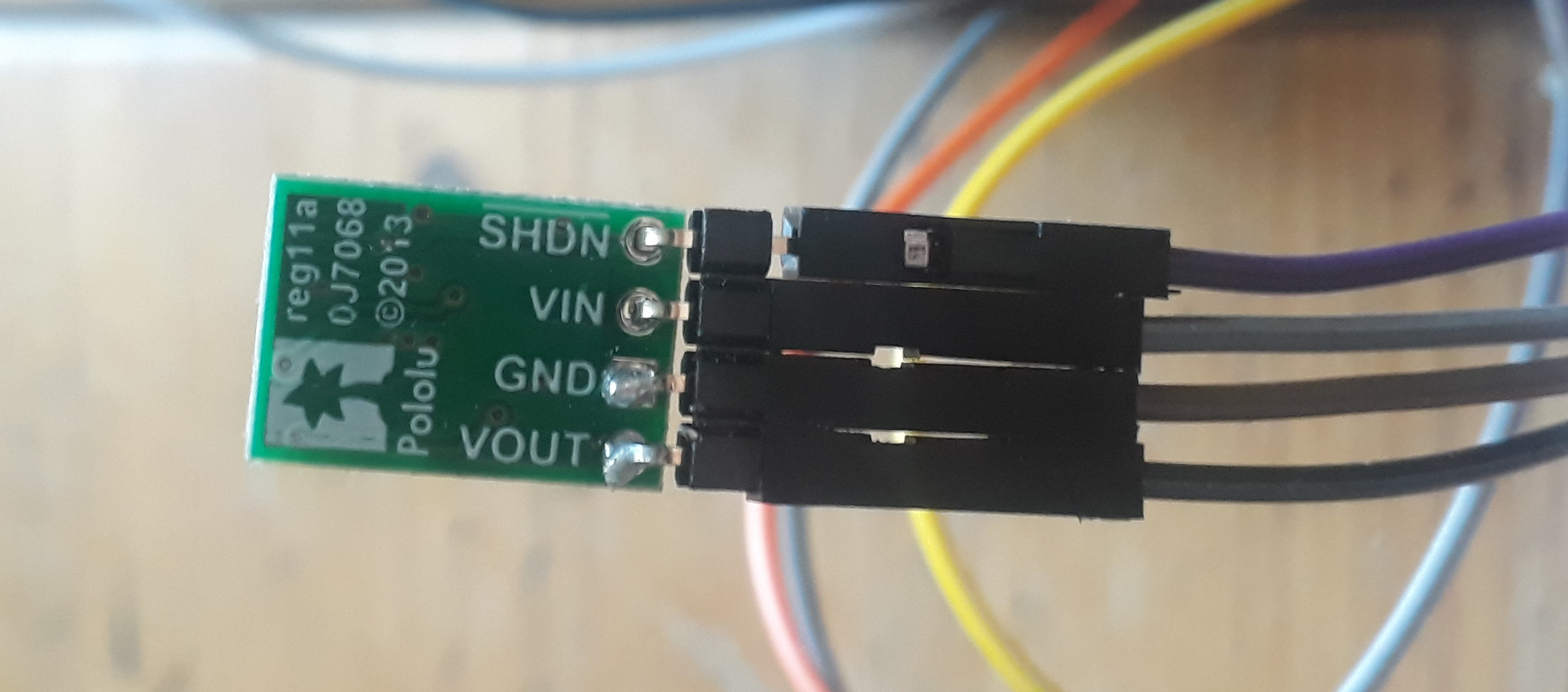
Power source is a Li-Io 18650 3.7V (measuring 4.1V since its still charged). The LDO gives me constant 3.3V (logic voltage) and the voltage regulator Popolu S10V3F8
measures constant 9V at Vout (supposed for motor/solenoid voltage)
and Vout1/2 only give me around 3V
The solenoid is latching.
Please note, our company name is “Pololu”, not “Popolu”.
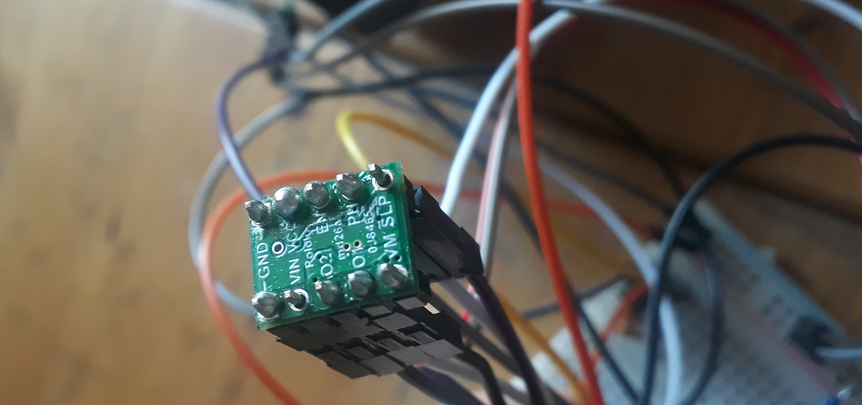
My main concern right now is that your soldering does not look great, and there are two pins on your driver that are not soldered at all which can cause intermittent connections and potentially damaging voltage spikes. You might check out the Adafruit Guide to Excellent Soldering, which is a useful soldering reference.
In the schematic, the driver is powered through the VM pin, but then in your pictures, nothing is connected to that pin. You do have a jumper wire connected to the VIN pin, and it would be fine to power your DRV8838 from either VIN or VM, but your VIN pin is not soldered. Given that error, it might also be wise to go back and double check that all of your connections match your schematic.
- Patrick
Sorry, for the getting the company name wrong.
Usually i have the VM pin connected like in the schematics but when i took the picture i had it connected to VIN just to try if something was off with the VM pin. But its the same behavior.
Thanks for your thorough investigation with the schematics. I’ll redo my soldering with the guide you provided me and hope that this is just due to bad soldering by a newby 
i resoldered and the measurements at Vout1 and Vout2 are the same. BUT i noticed that the voltage coming form the voltage regulator Popolu S10V3F8 only is 9V if i dont switch PHASE/ENABLE pins. As soon as i want to “drive” the motor the output voltage drops to 3V (thus explaining the low voltage i measure at Vout1/2)
It that (S10V3F8) supposed to behave that way or may this be the actual issue?
Please note, as I stated before, our company name is Pololu, not “Popolu”. Also, it looks like you are misidentifying your regulator; if it is outputting 9V you should have the S10V3F9. (We do not have a S10V3F8).
It seems like your circuit is not able to supply enough current for your solenoid. Can you measure the voltage at the battery output to see if it also drops when you try to drive the motor? That should help you tell whether the limiting factor is the battery or the regulator. Could you also post specifications or a datasheet for your solenoid?
- Patrick
sorry for the typos. It is the pololu S10V3F9. The voltage at the battery is stable. It only drops after the regulator. I replaced the regulator with the same type and it now drops to 5-6V “driving” the motor.
The solenoid vendor (Gardena) issued the following specifications (and as far as the discussion boards tell this has been proven to work)
Open: 9V DC, +300 mA, 250 ms
Close: 9V DC, -50 mA, 62,50 ms
I am not sure what discussion boards you are talking about; could you post a link to them? It seems fairly certain that the S10V3F9 is underpowered for your solenoid. Based on the maximum output current vs input voltage graph at the bottom of the S10V3F9’s product page, it looks like the maximum current you should expect from it using your battery is maybe 250mA, which is lower than what your solenoid is rated to draw when it opens.
With that in mind, you might consider replacing your regulator with a U3V12F9 step-up regulator which should be able to handle more power in your application (though your margins might still be pretty close) and has a similar size. (It is actually a little smaller.) Alternatively, if you want to be sure you have a powerful enough regulator and size is not a major constraint, you might also consider our U3V70F9 step-up regulator.
- Patrick
The circuit i build is from here https://github.com/jnsbyr/esp8266-gardena1251 where there are two versions (capacitator and h-bridge). I chose the h-bridge design.
The author has implemented both designs and was able to control the solenoid as far a the Readme tells me.
But i’ll go with the U3V70F9 just to be sure. Hope that will help
1 Like