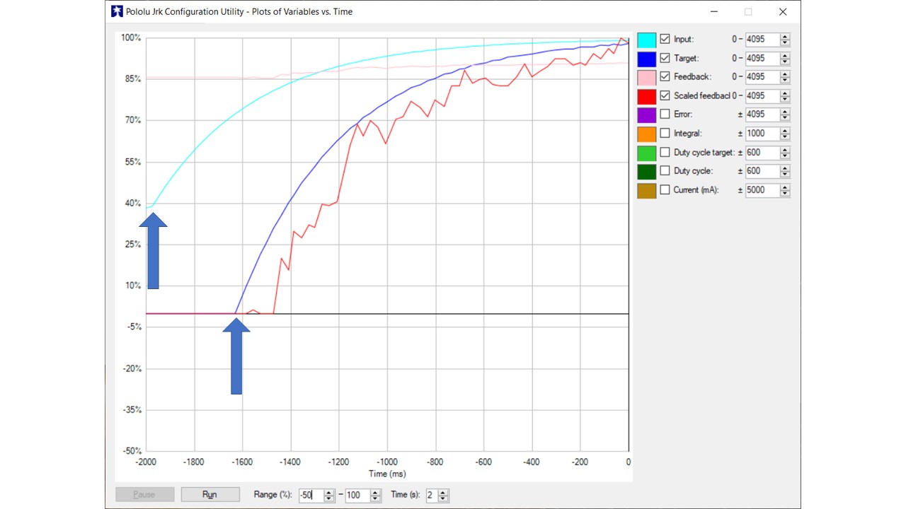
Hi, I’m having a huge delay from the input signal to the target signal. Both the input signal and feed back are analog, PID period is 3 msec. The set up blocks are attached. The graph shows about a third of a second delay from the input signal before the target signal changes. What can be done to eliminate this delay? Thanks,
Doug
Hello, Doug.
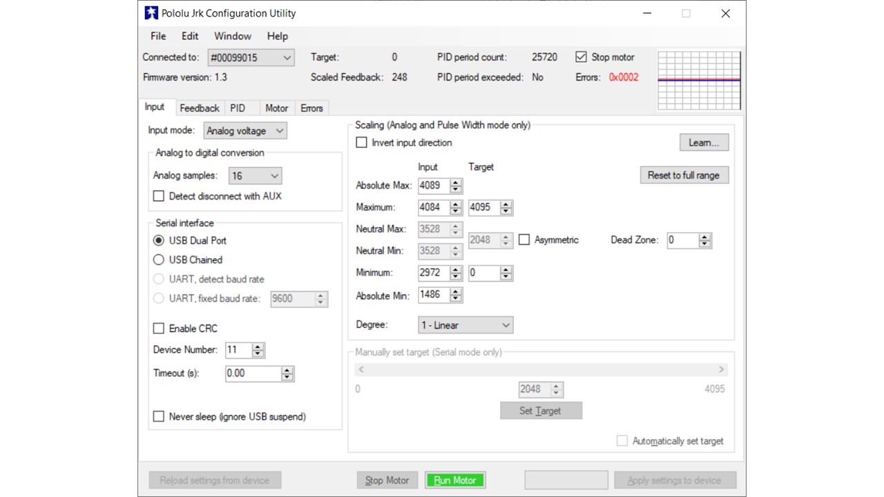
It looks like the time difference between when the input changes and when the target starts changing is caused by your input scaling settings. Any input below the configured “Minimum” will be mapped to a target of 0. So, the target will not change until your input is above a reading of 2972 (which is about 3.63V).
You can find more information about the analog input scaling in the “Input Options” section of the Jrk user’s guide, under the “Input scaling” heading. You might consider using the “Learn…” button and walking through the input setup wizard to automatically determine the appropriate values.
Brandon
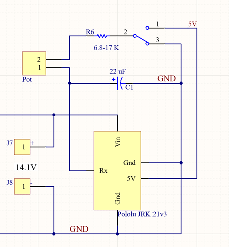
Thanks Brandon, that did help. I used the Learn button but should have realized that the numbers did not seem correct. My input is charging a capacitor from ground to 5 V both provided by the jrk. Setting the input to more realistic 0 to 4094 eliminated the delay but there is a new problem. Before the cap starts charging, with the input basically at zero, I am having a very difficult time holding the position still. The position jumps around constantly. Plus, the input is above 20%. Any help would be appreciated.
Here is the schematic used.
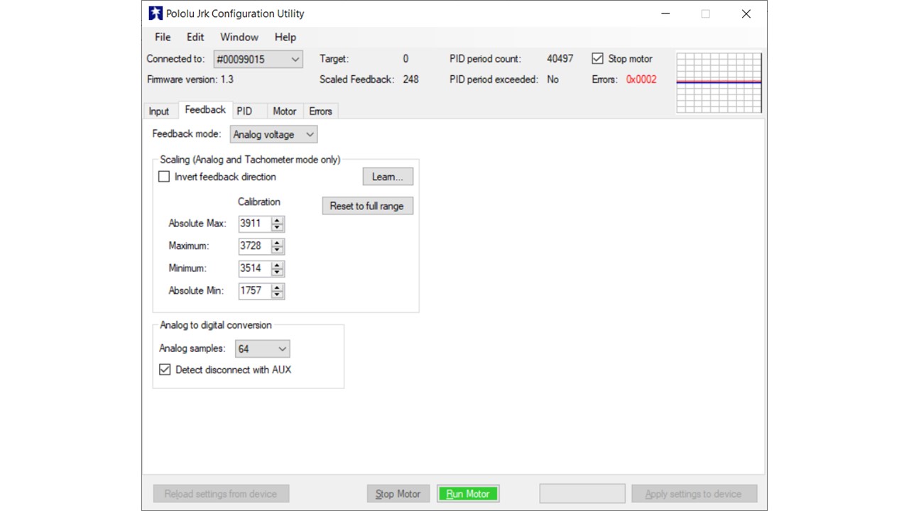
It looks like the difference in your minimum and maximum feedback scaling values are only ~200 units apart (which is only around 0.25V). Is that really the full range of your feedback signal? With that narrow of a range small amounts of noise on the feedback signal will result in large variations in the scaled feedback, so that could be contributing to the instability. Similarly to the input scaling, there is a “Learn…” button in the “Feedback” tab that can help calibrate those values if you have not done so already.
You might be able to get it performing better by re-tuning your PID coefficients, and please note that re-evaluating your PID coefficients might help whenever you change your feedback scaling values.
Brandon
Those are the values that were obtained using the learn method and it repeated again this morning. However when I use a meter to measure the resistance of the 10k pot, the difference between the two endpoints is over 2k or a 1v swing for the feedback.
I found out what I was doing wrong. It helps when the AUX and FB lines are correctly connected to the potentiometer… Thanks for your help Brandon.
1 Like