I design robots and we are trying this Jrk because it’s cool. We have put this in a few robots we ship to customers, testing everything of course.
Problem is, in just a couple months we’ve received two failures on this board (second time even before it was shipped).
-
Symptoms: Nothing happens because no input is detected according to Jrk Configuration Utility. It shows 0 uS no matter what. Replacing with a hobby servo, that works fine from the output we are generating.
- Tested with a scope directly on the RC pad of the Jrk and the RC pulses look clean and timing is correct.
- I’ve even tried reloading settings but of course no difference, it was already programmed correctly.
- I’ve temporarily changed the Jrk to Serial input and then can move the motor by the slider in the configuration utility. Never found any way to make the board work again with RC.
So what could be wrong? It’s just 5 V RC signal but I wondered if it only handles 3.3 V signals but that wouldn’t make sense if it’s compatible with standard servos.
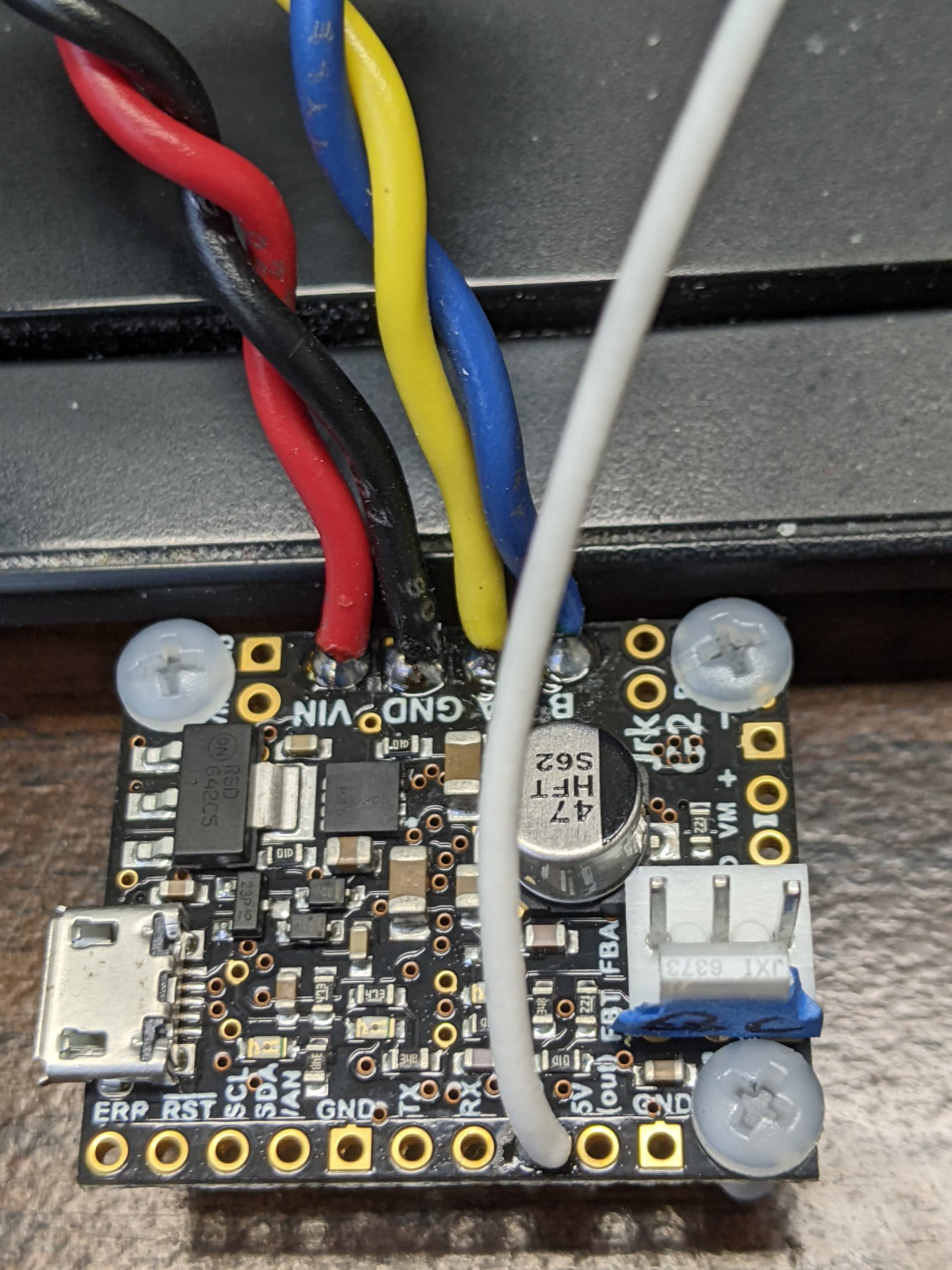
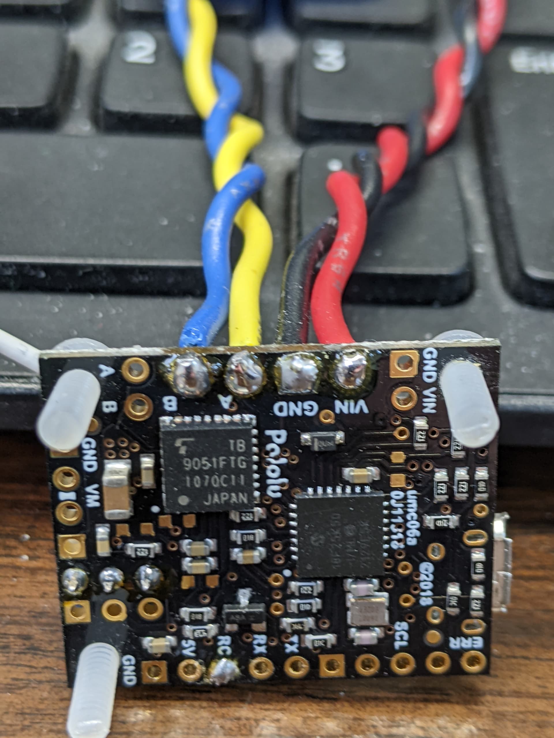
I am sorry to hear you are having problems with your Jrk controllers. A 5V hobby RC servo signal should be fine. Do both of the two problematic Jrks have the same behavior (i.e. reporting 0μs pulse width for your RC input)? Could you post more details about your system? For example, what is providing your RC input and how is everything connected? Could you post pictures of your setup that show all of your connections, including some close-up pictures of both sides of the problematic Jrk controllers?
Also, could you post scope captures of the RC input that you mentioned testing?
Brandon
I have over 50 years experience with electronics, just sayin I’m not asking what’s wrong with my homework.
Hopefully I can satisfy enough design without posting sensitive company designs. If you really need all this extra, seems to imply that the Jrk is not fully compatible with all other hobby radio systems (at least Airtronics, Hitec, Futaba for Robotronics the past 23 years). I say that because we’ve never had any trouble with all those plus our own “power servo” design which this was to replace.
We just got a shipment of the obsolete H-Bridge chips from our own design so we’ll go back to that while working out this Jrk. Ours isn’t as smooth, no PID settings, but at least it has worked solid with standard RC input for several years.
Here are some details:
- Power is 12V 35Ah SLA battery, connect (-) to Gnd and (+) to VIN on Jrk.
- Jrk drives a motor with gearbox to turn a character’s head, typically very little stress. We’ve done a stall test after this problem and measured (with a cheap DC meter) less than 2 Amp. Much less in normal running. The latest one that failed was after we tested a couple days (they work, then stop). It had not been stalled that I know of. I don’t believe it could be a high power issue since I confirmed these still control the motor properly if I change input and control with the slider on Jrk Configuration Utility.
- A and B drive the motor.
- Feedback pot (of course still works): Sides go to POT-(2) and AUX(4) if I’m reading Jrk labels right. Wiper goes to FBA(6). Those would be pin numbers on your 3X2 header footprint if pin(1) is the square pad.
- RC signal from our servo controller is soldered to the RC pad on Jrk. Since both are powered by the same battery, Gnd is common but no extra signal Gnd was added here.
- RC pulse widths in this robot version come from our board based on Arduino Uno R3 design so it runs sketches. It uses the standard Servo.h library.
- Scope shows 20 mS framerate (50 Hz) and obviously, ranging from 1.024 to 1.844 mS and high of 5.12 V (low 0 V)
- No ringing detected on the square wave (as I said it is clean signal).
- I saw another post mentioning to make sure there is continuity from Gnd of the Jrk to Gnd of my servo controller so yes I verified that again.
Thank you for the additional details. We have sold many thousands of Jrk G2 controllers over the past five years and have not heard of problems like this from other customers, so it seems like something out of the ordinary is probably going on here. As a first step, I recommend trying to figure out what on the Jrk is failing. Here is a the schematic of the RC input circuitry for reference:
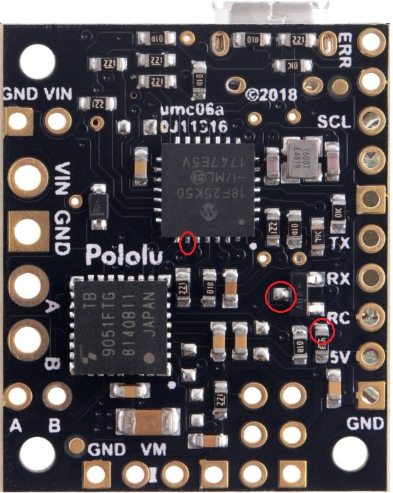
Could you try looking at the microcontroller’s RC input pin to see if the expected signal is reaching it? The signal on that pin should be the same as your RC signal except inverted. I have circled the nodes where this signal can be accessed on the board:
Brandon
Yes thanks, the schematic helps me trace further. I see the same signal on the MCU pin as the output of the transistor. That looks like a good signal (inverted from input), ranging 1v to 0.1v square wave. I attached scope data which didn’t generate GIF like I had before so maybe you can view the PCX drawing.
ALL0010.zip (10.6 KB)
The voltage on that node should reach 5V when your signal is low. Can you disconnect your signal from the board entirely and measure the voltage on that same RC node, and can you also measure the voltage on the 5V output pin? Also, can you post some pictures of your board?
Brandon
Getting interesting. The 5V pad measures 4.74v, I assume OK, although your on-board regulator measures 4.97v so there is some voltage drop. At the MCU where I saw the 1v signal, I actually had two different problematic results in two tests with my RC signal unplugged. The first test, touching my meter showed around 1.7v RMS and immediately the motor turned to one of the configured limits and stopped (sorry didn’t test with o’scope to see what noise it mistook for RC signal). Removing the feedback pot, touching my probe again continued turning in the same direction even past 0 on the pot (it is continuous and wraps around). I then unplugged everything to take photos but…
Through my camera screen I figured the solder didn’t look great between the RC and 5v pads although never detected any shorts which I had checked for before other testing. Still, just flux could cause trouble in some cases, so I retouched it and removed flux. Then I plugged in everything to see if it works any different…
Now it is back to not moving at all; Now I only measure 1v on that node while my RC signal is removed instead of 1.7v.
I’m assuming you mean pictures of your board which failed, not my servo/switching control board in the robots.
Thank you for the additional information and pictures. Part of the reason for the pictures is to see the boards in context, (e.g. how long are the wires and how are they routed). For instance, this single RC signal wire is worrisome, and it might be helpful to see what the full path is for that RC signal return current.
At this point it’s probably best if we took a look at your two failed boards. If you’re up for sending them back to us, please email us with your order information and reference this forum thread so we can get an RMA set up for you.
Brandon
Thank you for the explanation of what you need in photos. The RC signal wire from Robotronics servo board to your RC in is just over 5 inch (136mm). The ground path is longer because of my colleague removing signal Gnd from that cable being worried about a ground loop problem. I estimate both power Gnd wires travel 1.2 meters to the base where they connect at a common point. You will never see that long ground path cause this failure we are looking at, however.
Some things I think we can already be sure of: (1) your Jrk has failed, does not work. Our robot still works fine just replacing that. (2) there is no sign of design flaw with the ground path. To prove it, the signal not only looks good but works perfect on your working boards (and our power servo boards). To test signal, I’m referencing the ground of your board so the scope is showing what your board is seeing. Most importantly if I replace the failed Jrk with another Jrk then it works fine. (3) maybe 1 to 2% of your boards have failed so that makes it highly unlikely that our design is using your board incorrectly assuming yours is designed as you say.
I would have to remove your surface mount transistor to be sure if it is the MCU input clipping to 1v and not the transistor, but it sounds better if we can send it to you to see what your board is doing.
I’ll work on getting the RMA; I have both now and preparing them to send.