I’ve used servos before but I’ve never set up a motor controller.
I’m using a Jrk G2 21v3 with a potentiometer I salvaged from a 5v servo. The motor / Jrk are running on 24v.
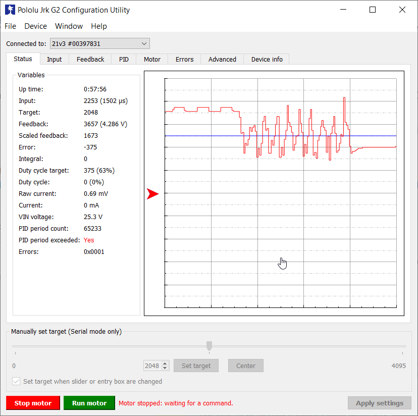
The pot is reading relatively static values while the motor is stopped, but when I run the motor the motor moves back and forth trying to maintain position and the feedback line is also going all over the place. Is this a configuration issue or a bad potentiometer?
I would assume it’s a bad pot, but the issue is only present while running the motor. The readings on the pot are consistent when I disconnect the chain from the motor and manually move the assembly to either end of its limits.
I’m using RC input but while this was happening the input was a consistent PWM of 1500. Other than that my configuration is all of the defaults that are recommended in the docs, I haven’t changed any values or even found a value that would seem to help. The analog samples option in feedback did reduce the issue when increase from 128 to 1024 but it did not stop it in a meaningful way.
In the attached image, I hit run motor and that’s when everything starts spiking. When I hit stop it evens out again.
I recommend changing the input mode back to “Serial / I²C / USB” and using the slider in the “Status” tab of the Jrk G2 Control Center as your input so you can have more direct control while troubleshooting the feedback. Then, you can change back afterward.
I am not sure what you mean when you say that your configuration is all of the defaults recommended in the documentation, since we have different recommendations for various setups. Have you tried following the instructions in the “Setting up analog feedback” section of the Jrk G2 user’s guide (going through each heading, including “Tuning the PID coefficients” at the bottom)? If so, could you post a copy of your settings file? You can save a copy of your settings file from the “File” drop-down menu of the Jrk G2 Control Center while the controller is connected.
That’s the guide I meant, attached the settings file for you. I did miss some of those troubleshooting steps.
I measured the volts on FBA and saw 4.05 while the interface said 4.35. Interestingly, I saw only 4.15 v coming from the aux pin.
It seems I had a fundamental misunderstanding of PID tuning, for some reason I thought that only applied to how the controller actually moved the motor and not how it read in the feedback (idk tbh probably just too used to ardupilot and I was thinking the pot would be equivalent to user input and the user input was oscillating or something like that). Reducing it from 1 to 0.5 is already much better and I’m going to continue down that path and see how much better it can get