I have two new JRK G2 18V27 and have started to make the basic setup using the Configuration utility and got error message ”Motor Driver Error” after approx 15 minutes when testing ”motor A”. Got the error when the motor was running and no setting was changed. The error appeared yesterday so I turned it off when I didn’t find the reason for it but it’s still there when I started up again today so it’s not related to over-temperature from the test. The error appear when I connect the jrk by the Configuration utillity and don’t disappear.
Made some tests with combinations of jrk’s and the motors…
”Motor B” + ”JRK card B” works fine
When I connect ”motor A” to ”card B” the combination also works fine
When I connect ”Card A” to ”motor B” the ”Motor Driver Error” is displayd so the error is related to the card and not the motor.
Other info…
Red LED and green LED are on (steady, not flashing ) on ”JRK card A”.
Measured input voltage is 12,14V and the Configuration utility display VIN voltage 12,2V.
Configuration utility settings: Hard current 25,65Amp and Soft current 24,0Amp.
Motor driver Error setting: ”Enabled”
Replaced the power supply but still the same error code.
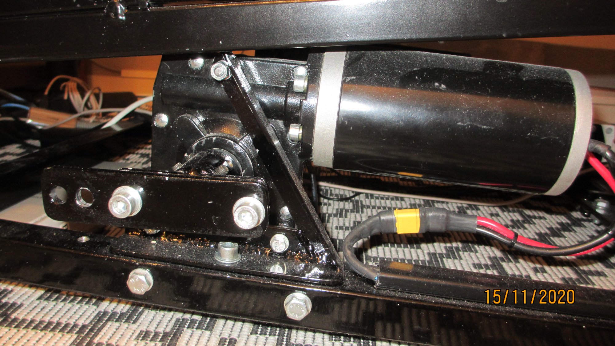
Use 12V, 200W worm gear motors, nominal current 25Amp and no load on the motors during tests.
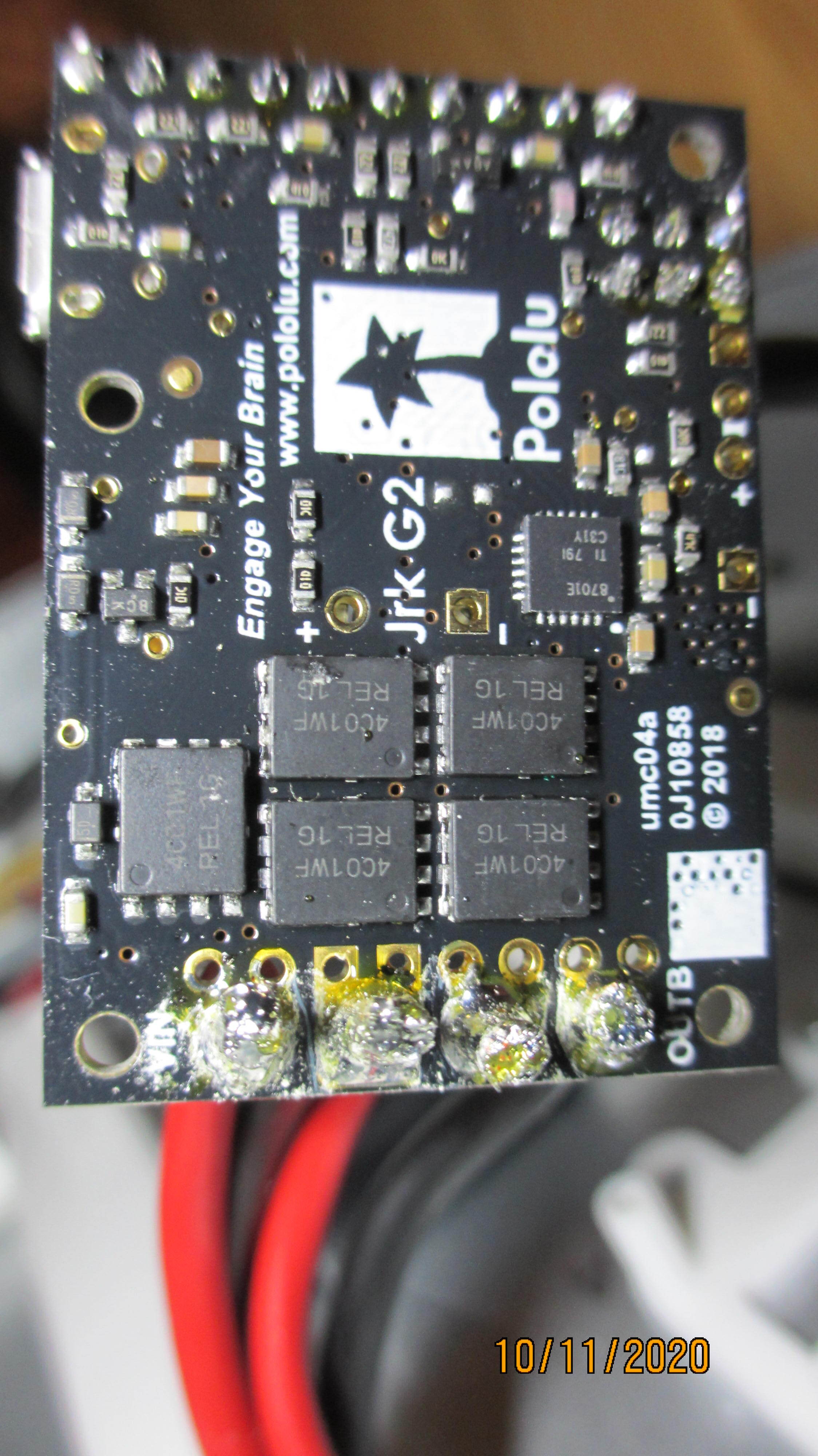
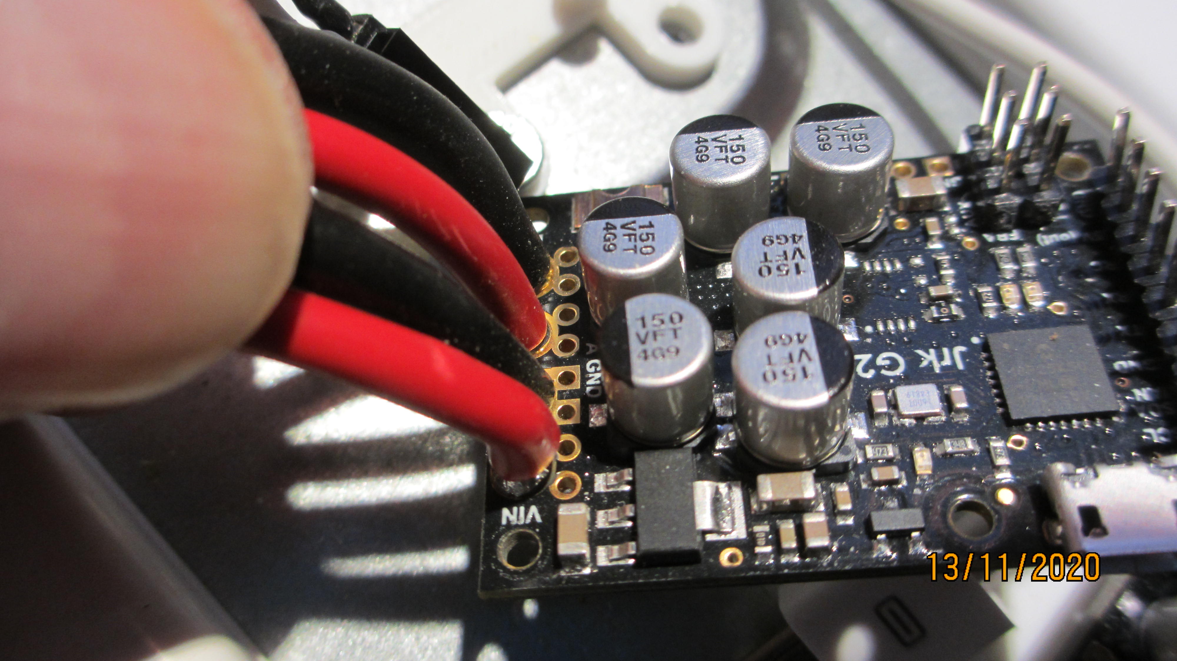
The jrk card and connections looks good. (pictures attached)
Just to clarify, are you saying that the Jrk is always reporting the motor driver error now, even when not running the motor and just connected to USB?
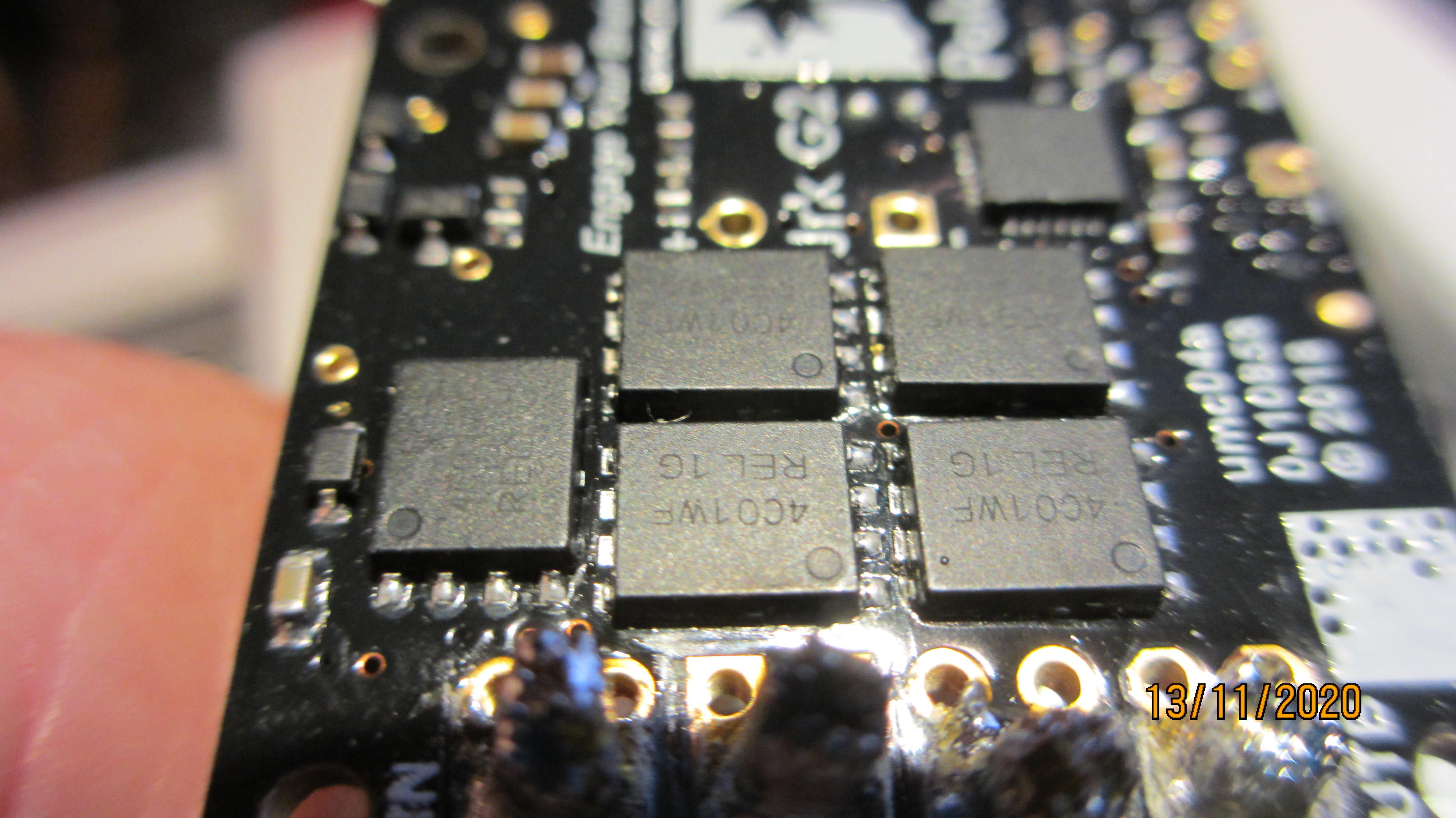
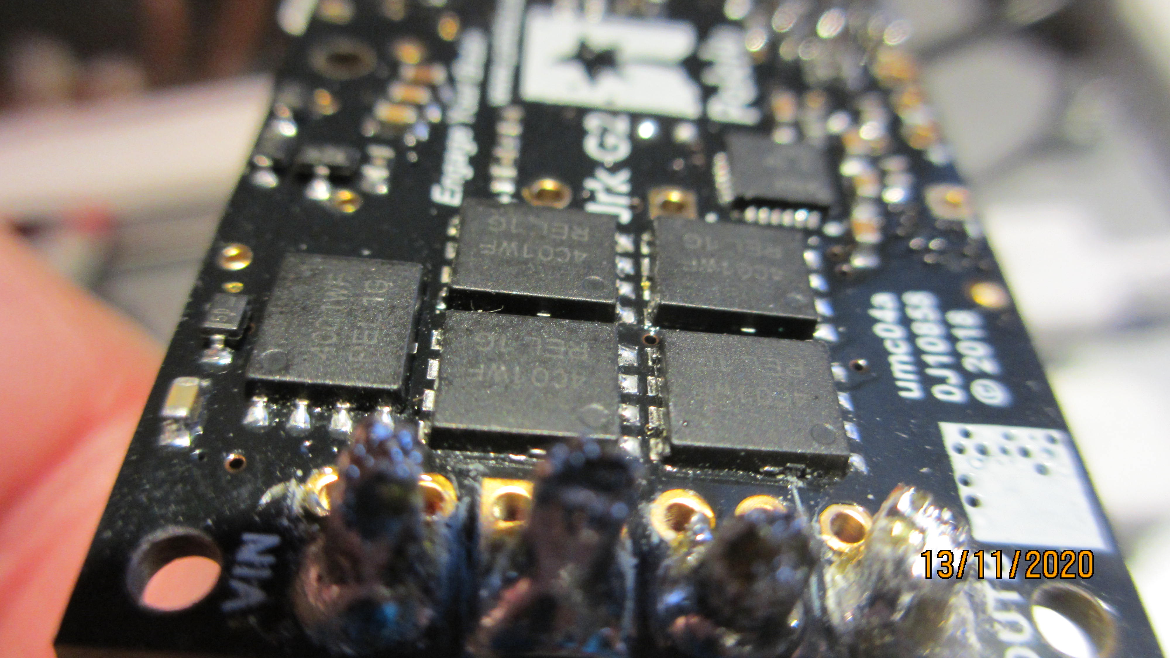
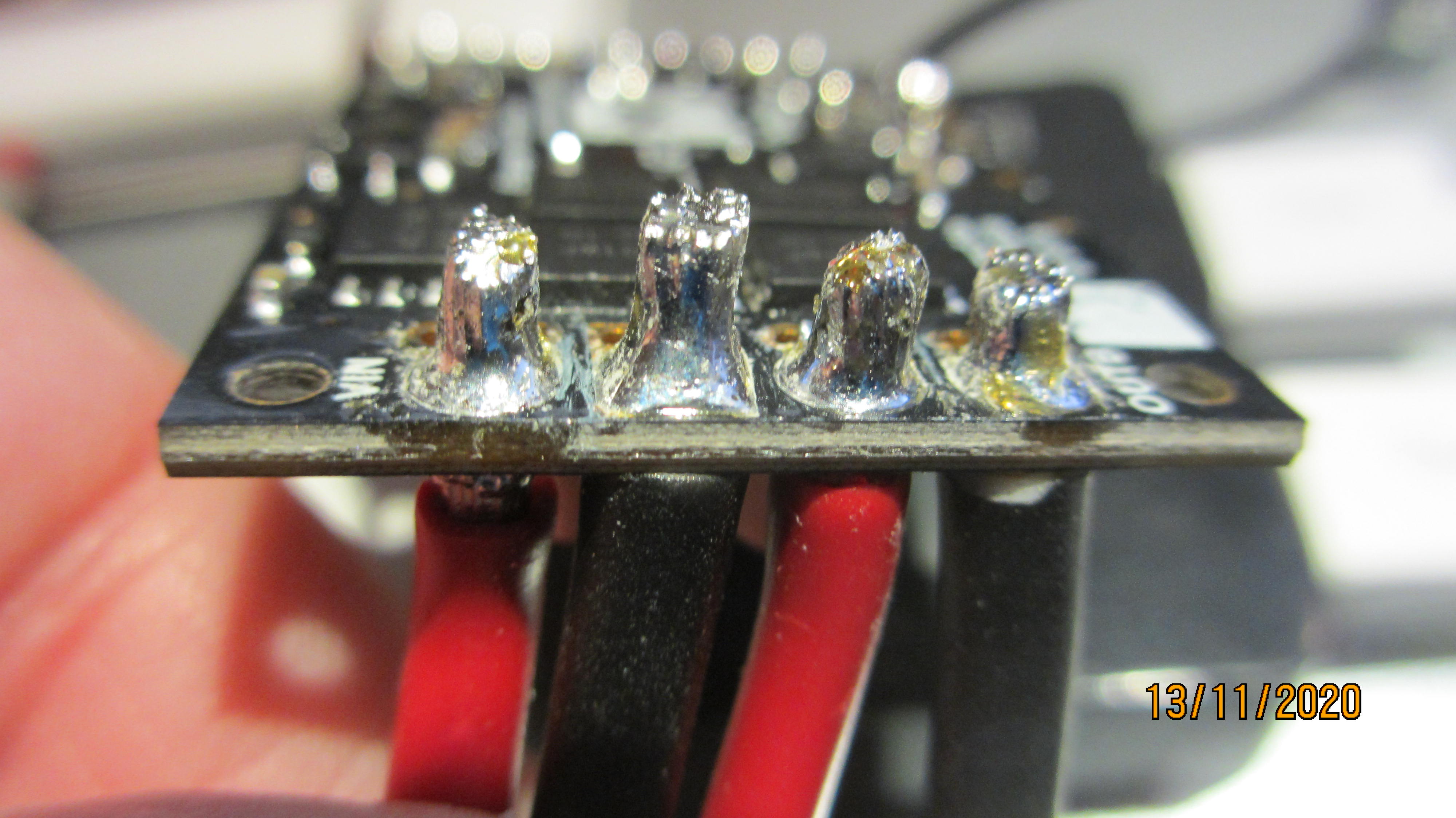
The motor driver error on the Jrk G2 can be caused by the motor driver’s over-temperature or over-current conditions. However, as noted in the Jrk G2 user’s guide, the Jrk does not directly measure the temperature of the MOSFETs, which are usually the first components to overheat. It is hard to tell from your pictures, but it looks like there might be some indication of damage to your MOSFETs; there are a couple of bubble-looking marks on them, but it is hard to tell if that is just some kind of debris or actual deformations on the MOSFET. You might also double check that none of your power or motor connections are shorting, as the solder on those pins looks kind of rough.
Yes, it indicate the error without running the motor and just the USB connected.
I don’t find any short circuit between the connection wires by visual inspection but I will check the motor/PS wiring with a multimeter. Is it OK to solder on one side only?
MOSFET’s looks good to me without any damage or bubbles on the surface.
Thank you for the additional information and pictures. If the motor driver error is triggering at all times, even when there is nothing but USB connected, it sounds like your controller was damaged in some way. Could you post more information about your motors, such as a datasheet? How was the motor running when the error first occurred (e.g. was it just running continuously in one direction, rapidly changing directions, or changing directions while going full speed)?
As far as the soldering, you do not need to solder it from both sides; typically you can get the solder to flow through the joint from one side, and from your updated pictures, the soldering looks like it is wetting to the pads nicely.
I got the error when I was changing direction using the Configuration utility with low speed and without any load on the motor.
Made some additional tests and measurements yesterday and the card looks to be broken now because the Power Supply is shutting down the output voltage when I connect the jrk. (the same PS works when connecting it to the other card/engine). And there is only 0,6 ohm resistance between input GND and the +12V output motor connection.
Have also been in contact with the manufacturer of the worm gear motor to get more data…
Motor type: 80ZYJ08
Rated voltage: 12V DC
Power: 200 Watt
Rated current: 25 Amp
Stalled motor current: 80~100A
Start peak current: 60~80 A
Motor speed: 3600rpm at no load
Worm gear ratio: 50:1
Rated shaft torque: 30Nm
Shaft output speed: 60rpm at 30Nm load
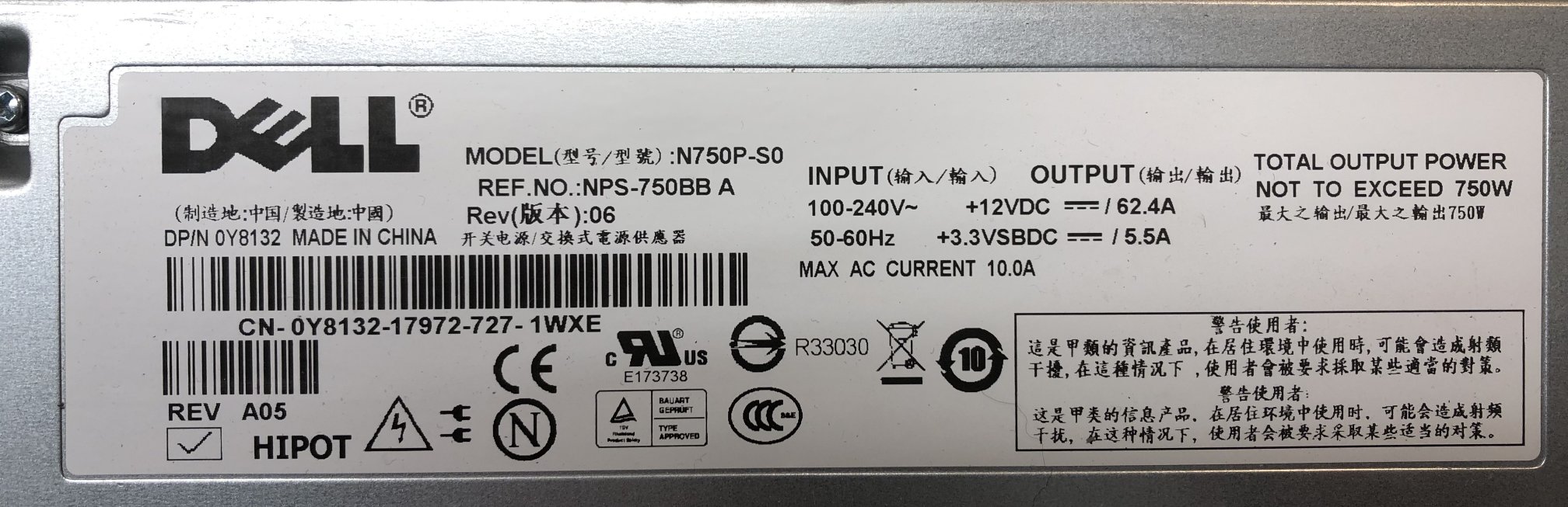
Power supply: Dell N750P, one for each card/motor
Voltage: 12V DC
Max power: 750 Watt
Rated current: 62,4 Amp.
Based on those specifications, the Jrk G2 18v27 is under-powered for that motor. Also, note that changing direction while the motor is moving can draw large spikes of current. If you want to try using your other Jrk for now, I recommend taking additional precautions, such as limiting the maximum acceleration/deceleration as well as the maximum speed.
If you want to try a controller that can handle more powerful motors, you might consider one of the RoboClaw motor controllers, such as the RoboClaw Solo 60A Motor Controller.
Can you please specify why the 18v27 is under-powered to the motor I use and what maximum peak current the JRK G2 18v27 can handle?
I found info in another thread that the configurable hard current can be set to 76Amp and will be regulated down to that limit so I guess the card can handle peak current much higher than 76Amp.
”For the Jrk G2 controllers there is a configurable hard current limit that can be set high enough to generally be out of the way (a maximum of about 42A for the 24v13, 53A for the 18v19, 64A for the 24v21, and 76A for the 18v27). It’s important to note that this hardware current limit on the Jrk G2 does not cause some shutdown; instead the current will get regulated to that limit, so it should be more practical than before to do things like safely deliver 30A to a motor that would otherwise want to draw hundreds”
My motors maximum current peak at start and when changing direction very quickly is according to the manufacturer 60~80 Amp. Max regulated current from the power supply is approx 63Amp so the PS willl also help to reduce the peak, probably not down to 63Amp but below the 76Amp if the motor try to consume 80Amp.
The JRK is listed as a ”Brushed DC Motor Controllers” with max continuous current 37Amp, rated current on my motor is 25Amp, 12 Amp less.
As described in your quoted paragraph, the values used there are intended to be “out of the way”, meaning they shouldn’t be reached during any kind of normal operation. You can lower that limit to something like 30A, but this will drastically reduce the speed and torque that your motor is capable of. Especially at the point where a controller has been damaged, being cautious by adding acceleration/deceleration and max speed limits (or switching to a more powerful controller) seems warranted.
The “rated” current of a motor is not usually a very helpful number, since it means different things to different manufacturers. For example, sometimes it refers to the current at which it is most efficient, other times it means the current at which it is outputting peak power, and other times it is actually referring to the stall current. The more important figures to consider are the stall current and the current you are expecting it to draw in your specific setup under load. We typically recommend choosing a motor controller that can continuously handle the stall current of your motor; however, with larger motors, that is not always practical. You listed the stall current of your motor as 80-100A; please note that changing directions at speed can draw quick spikes of current upwards of double the stall current. How you are using the motor is also a consideration. For example, if you are limiting the acceleration and always moving the motor in slow gradual changes, that requires very different considerations than something like a balancing robot that is constantly changing directions at high speeds (which puts a lot of stress on both the mechanical and electrical components).
Additionally, the max continuous current we list on the product page is 27A without additional cooling. Can you clarify where you saw 37A?
Hello Brandon,
Sorry, the 37Amp current is a mistake by me , it’s of course 27Amp. Found a written note made by me about 37A and have been looking around on the site but don’t find it so it’s a writing mistake by me.
The power supply works fine now when connected to the JRK. The issue was related to a pin in the Dell contact connected to the PS which turned off the output voltage.
But I still have the Motor Driver error… so if the 200W motor is to big for the JRK and will burn a new JRK card I have to find another solution.
Is there any easy way to check if the card is broken or not?
The simplest test would be to connect the Jrk to the Jrk Configuration Utility with only the USB connected. If the Jrk is reporting a motor driver error when nothing else is connected to it, it is damaged in some way.