
I recently finished up a build using a Raspberry Pi with a JRK G2 21v3 and a Micrometal gearmotor with the Pololu magnetic encoder for a speedometer project I’ve been working on for a while now, but I’ve got some strange motor twitching happening that I’m unsure how to deal with. I have a dual shaft micrometal gearmotor running the magnetic encoder for speed feedback to the JRK. The JRK is connected via USB to the Pi and I have a Python script running as a service in the background that watches for inputs on a GPIO pin from the ECM speedo output in my car. My script counts pulses in a fixed time and sets the appropriate target value for the JRK to drive the original mechanical speedometer in my car at the correct RPM. That part seems to finally be working really well, but I’m getting some odd behavior when sitting still. With the car just idling at full stop, the speedo will occasionally twitch a large amount very briefly. I had originally thought that the JRK didn’t like having the “zero” target (2048 value) being sent over and over, so I updated the code to only send the set target command if it reads a speed different from what it read the cycle before, but it’s still twitching on me. Any idea what I should be looking for? I had originally thought that maybe my car was just too electrically noisy for 3.3v signaling, but it only seems to happen at idle. My understanding was the magnetic encoder also had some hysteresis built in to help prevent spurious triggering if it stopped at an edge, so I think that should rule that out, but hard to say. Just looking for some ideas on what to start measuring to see if I can find this rogue pulse.
Hello.
I suggest simplifying your setup until you can find the source of the problem. For example, if you stop your Python script service routine from running, and use the Jrk G2 Configuration Utility to control the motor from the “Manually set target” slider in the “Status” tab, does it still twitch if you leave it set to 2048?
You can also use the graph built into the Jrk G2 Configuration Utility to try to get a better idea of what is going on. Clicking on the graph brings up a customizable pop-up version of the graph. I suggest looking at the “Target” variable to see if it is getting change when you expect it to be a steady 2048.
Also, you could double check that the “Errors” tab of the Jrk G2 Configuration Utility is not reporting anything concerning; in particular, you can check to see if the “Count” value for any errors increases when the twitch happens.
Brandon
Okay, did a little more checking and think I know what is going on now, though need to figure out how I want to fix it. For whatever reason when the motor stops, it’s stopping with a feedback value of 2080 instead of 2048. The target is steady at 2048 the whole time. I think the error is building up for the PID algorithm and twitching the motor to try to make up the difference. I think I just need to set a deadzone for the feedback at what should be zero motor rpm. Need to dig around in the settings and see what I can find. I also need to see if it’s always coming back to 2080 every time I power cycle the system or if that was just where this one time ended up for some reason.
I thought about this some more and I’m not sure if a deadzone is really the right answer or not, but I think some of that is just my understanding of how the deadzone setting works when it comes to frequency feedback. The manual description:
The “Feedback dead zone” option sets the duty cycle target to zero and resets the integral whenever the magnitude of the error is smaller than the feedback dead zone amount.
The second part sounds like what I’m looking for (reset the integral when the feedback is within a set range of the target), but I think I only really want this to happen at “center”. The way I’m interpreting that description is that any given target value is really more like a range and not a specific target, so any deadzone value becomes more like a feedback resolution adjuster. When I think “deadzone” I think of a traditional joystick controller where there is a small range of values around the center position that are effectively ignored until the signal exceeds a certain threshold (maybe threshold value is a better term?).
Am I just misinterpreting how the feedback deadzone works and it really does only apply at “zero”, or does it apply over the full range of feedback values? If it does apply to the full range I’m more inclined to do some reworking in my code to just send a feedback value of 2080 at zero speed (still not sure why that is the feedback value it settles on, but it seems to do that consistently). My feedback values increment in steps of 12, but if I had to set the deadzone to cover the difference between 2080 and 2048 I’d be losing 3 steps either direction of whatever target value I have, which is more than I’d like to give up.
The feedback dead zone sets the duty cycle target to zero and resets the integral whenever the error is smaller than the specified value; it is probably more helpful for closed-loop position control using analog feedback.
Just to clarify, when your motor is completely stopped, you are still seeing a feedback value of 2080? What is the scaled feedback value reporting? When the motor is stopped, the encoder signals should be as well, so I would expect the frequency feedback to report 2048. Could you post a copy of your Jrk G2 settings file? Also, which micro metal gearmotor and encoder are you using?
Brandon
Yeah, I was thinking the dead zone setting was really more for positional feedback and not frequency.
And yes, the motor is not rotating at all as far as I can tell. I’m using this motor: Pololu - 10:1 Micro Metal Gearmotor HPCB 12V with Extended Motor Shaft with this encoder: Pololu - Magnetic Encoder Pair Kit with Top-Entry Connector for Micro Metal Gearmotors, 12 CPR, 2.7-18V.
Settings file should be attached.
jrk_settings.txt (1.9 KB)
To my best understanding the scaled feedback and feedback values are the same and both reporting 2080 when the motor is stopped (sorry for the picture quality, hard to take a picture of a screen).
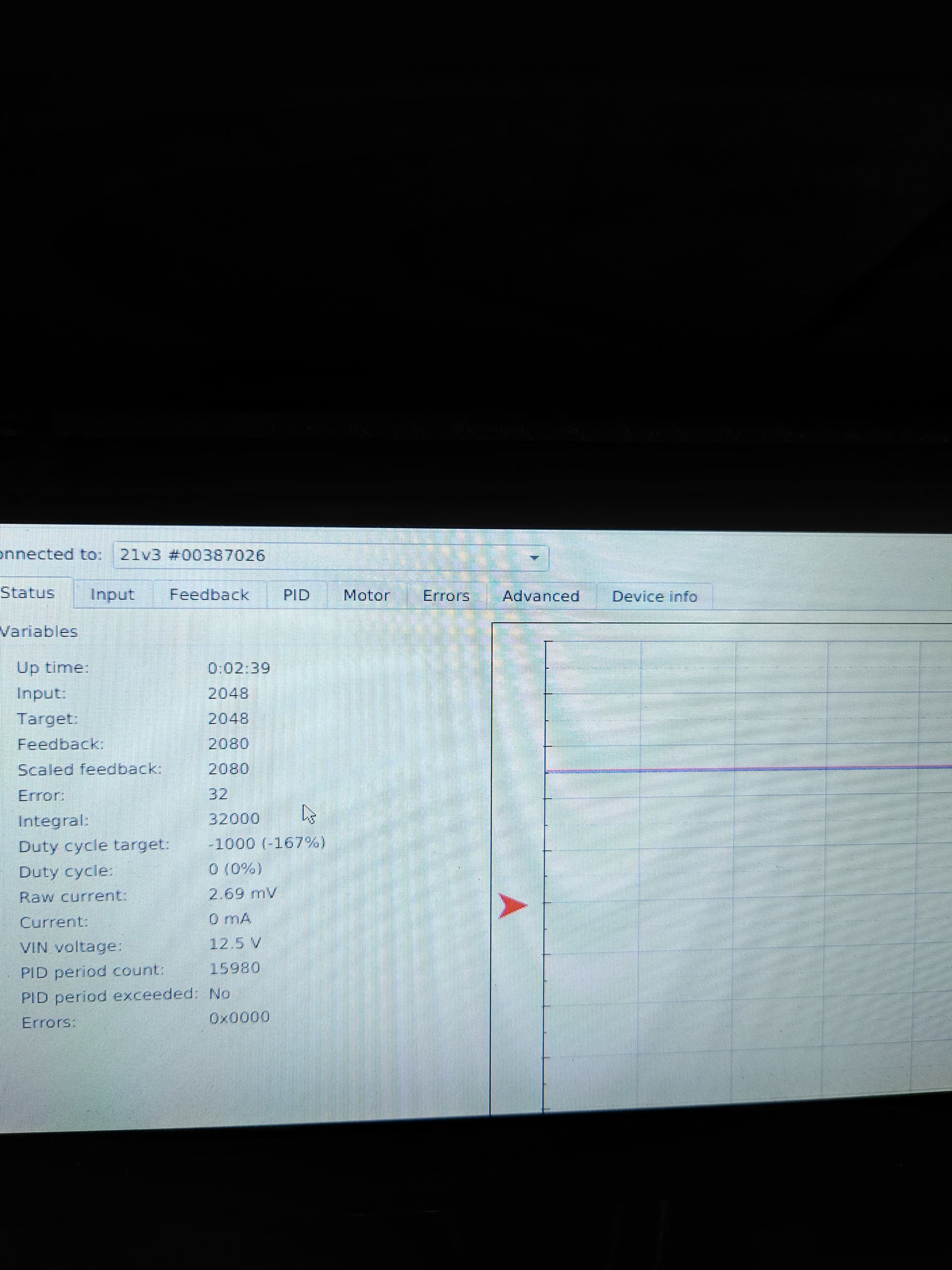
After the motor moves for the first time, it seems like it always settles back at 2080 instead of 2048 when it is told to “stop”.
To clarify a little more, I know the encoder has dual outputs, but I’m only using one of them. Feeding it 5v off the reference voltage on the JRK and returning the encoder back to the FBT pin. The other encoder output is just an open wire.
Thank you for the additional information. I was able to recreate your setup here with the same products; however, I could not reproduce the same twitching problem you described when I set the target to 2048 (although it does periodically move the motor if I set the target to something really slow like 2085). So, I am still not sure what might be causing that problem. You might try using the “Force Duty Cycle” or “Force Duty Cycle Target” command when you want the motor to stop (and clear the integral) instead of setting the target to 2048. If that works, you could also use the same method as part of the procedure for switching directions.
Brandon
Hmm interesting. I’ll have to look into those other commands. Honestly that would probably make more sense anyway. I’d prefer to “turn off” the motor at 0 speed so to speak, so forcing a 0 duty cycle makes sense to me. For the time being I’ve just tweaked my code to command a 2080 target, but I know that’s not really the “right” way to fix it. I’ll try to dig into the documentation some more and see what I can come up with. Thanks for the help so far!