JRK daisy chaining, not able to get correct feedback

My setup is 2 actuators with feedback connected to two JRK21V3. TX lines from JRK’s feed into 74LS08 Quad 2-Input AND Gate. Output from AND gate and RX lines from JRK’s are connected to Arduino. When not daisy chained the modules work fine individually and I am able to transmit and receive serial data without a problem. With the AND gate connected I can apparently receive transmissions from one of the JRK units, but not the second. My test code is attached. My output from the test code is attached. The output from actuator 12 matches the second reported position from actuator 11 which seems odd. So my apparent problem statement is I cannot receive position feedback from actuator 12. For reference both actuators accept the move statements fine and respond accordingly.

My code

[code]#define RX_pin 4
#define TX_pin 6

#include <SoftwareSerial.h>
SoftwareSerial mySerial(RX_pin, TX_pin); word target = 0;
int end_position;
char response[2];

void Move(byte device, int x) {
word target = x; //only pass this ints, i tried doing math in this and the remainder error screwed something up
mySerial.write(0xAA); //tells the controller we’re starting to send it commands
mySerial.write(device); //This is the pololu device # you’re connected too that is found in the config utility(converted to hex). I’m using #11 in this example
mySerial.write(0x40 + (target & 0x1F)); //first half of the target, see the pololu jrk manual for more specifics
mySerial.write((target >> 5) & 0x7F); //second half of the target, " " "
}

int GetRawPosition(byte device){
int rpos = 0;
mySerial.write(0xAA); //tells the controller we’re starting to send it commands
mySerial.write(device);
mySerial.write(0xA5); //raw feedback
mySerial.readBytes(response,2);
rpos = word(response[1],response[0]);
return rpos;
}

void setup() {
mySerial.begin(9600);
Serial.begin(9600);
Serial.println(“Setup Complete “);
Serial.println(””);
}

void loop() {
Serial.println(" “);
Serial.println(“Actuator 11 top of loop”);
Move(0xB, 100);
delay (5000);
end_position = GetRawPosition(0xB);
Serial.print(end_position);
Serial.print(” 100?, “);
Move(0xB, 1000);
delay (5000);
end_position = GetRawPosition(0xB);
Serial.print(end_position);
Serial.print(” 1000?, “);
Serial.println(” “);
Serial.println(“Actuator 12 starting”);
Move(0xC, 200);
target = 200;
delay (5000);
end_position = GetRawPosition(0xC);
Serial.print(end_position);
Serial.print(” 200?, “);
Move(0xC, 3000);
delay (5000);
end_position = GetRawPosition(0xC);
Serial.print(end_position);
Serial.print(” 3000?, ");
}
[/code]
My output

Setup Complete Actuator 11 top of loop 193 100?, 990 1000?, Actuator 12 starting 990 200?, 991 3000?, Actuator 11 top of loop 196 100?, 990 1000?, Actuator 12 starting 991 200?, 990 3000?, Actuator 11 top of loop 192 100?, 990 1000?, Actuator 12 starting 990 200?, 990 3000?,

Thank you for including your code and the output you get from that code. I glanced over your sketch and did not see anything obvious that would cause the problem you described. Could you try simplifying it down to just setting the target and reading the feedback of the jrk set to device number 12 (still going through the AND gate with both jrks set up)?

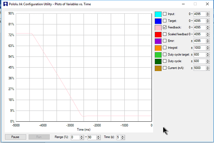
Could you describe what the indicator LEDs are doing on that jrk? Also, could you try opening the Jrk Configuration Utility and using the plot to monitor the “Feedback” to see if it shows the feedback moving as you would expect when the actuator is moved?

-Brandon

Another engineer here pointed out a mistake I missed when I looked over your code, so I wanted to add to my previous post. Since you are using the Pololu protocol, you will need to clear the most significant bit of the read variable command (e.g. you should use mySerial.write(0x25); instead of mySerial.write(0xA5);). Can you try making that change and seeing if it fixes the problem?

-Brandon

Thanks for the guidance. Code and output are included. I squeezed the code down to just actuator 12 (the one daisy chained to 11) and changed the feedback command from 0xA5 to 0x25. No luck on the output though. You also said “…you will need to clear the most significant bit of the read variable command …”. I’m afraid I don’t know how to do this. Google led me to a fair few sites on least significant bit, but it was a “bit” beyond me . Any advice?

Updated code:

[code] #define RX_pin 4
#define TX_pin 6

#include <SoftwareSerial.h>
SoftwareSerial mySerial(RX_pin, TX_pin); // RX (a), TX (b), plug your Arduino TX (b) to the RX pin on the JRK
word target = 0;
int end_position;
char response[2];

void Move(byte device, int x) {
word target = x;
mySerial.write(0xAA);
mySerial.write(device);
mySerial.write(0x40 + (target & 0x1F));
mySerial.write((target >> 5) & 0x7F);
}

int GetRawPosition(byte device){
int rpos = 0;
mySerial.write(0xAA);
mySerial.write(device);
mySerial.write(0x25); //raw feedback
mySerial.readBytes(response,2);
rpos = word(response[1],response[0]);
return rpos;
}

void setup() {
mySerial.begin(9600);
Serial.begin(9600);
Serial.println(“Setup Complete “);
Serial.println(””);
}

void loop() {
Serial.println(" “);
Serial.println(“Actuator 12 starting”);
Move(0xC, 200);
target = 200;
delay (5000);
end_position = GetRawPosition(0xC);
Serial.print(end_position);
Serial.print(” was returned - match 200?, “);
Move(0xC, 3000);
delay (5000);
end_position = GetRawPosition(0xC);
Serial.print(end_position);
Serial.print(” was returned - match 3000?, ");
} [/code]
Updated output:

[code] Setup Complete

Actuator 12 starting
0 was returned - match 200?, 0 was returned - match 3000?,
Actuator 12 starting
0 was returned - match 200?, 0 was returned - match 3000?,
[/code]
Plot 1:


Plot 2:

Thank you for posting your updated code. The 0x25 command is the 0xA5 command with the most significant bit cleared. So, to clarify, 0xA5 is 10100101 in binary, and by setting the first bit to 0 it becomes 00100101, which is 0x25 in hex.

I tested your updated GetRawPosition() function in a setup here and it worked fine for me. It looks like you are not getting any response back from the jrk. Could you double check to make sure your jrk’s serial interface is set to “UART, detect baud rate” and the device number is set to 12? Could you post the settings file for your jrk that is set to device number 12? You can save the settings file by choosing the “Save settings file…” option within the “File” drop-down menu of the Jrk Configuration Utility. If those settings are correct, could you try checking your TX, RX, and GND connections?

-Brandon

Looks like I have it set to “UART_FIXED_BAUD_RATE” and baud rate of 9600. I will test your suggestion this weekend. Thanks again for the support.

Config File:

INITIALIZED 0 INPUT_MODE SERIAL INPUT_MINIMUM 0 INPUT_MAXIMUM 4095 OUTPUT_MINIMUM 0 OUTPUT_NEUTRAL 2048 OUTPUT_MAXIMUM 4095 INPUT_INVERT 0 INPUT_SCALING_DEGREE 0 INPUT_POWER_WITH_AUX 0 INPUT_ANALOG_SAMPLES_EXPONENT 5 INPUT_DISCONNECT_MINIMUM 0 INPUT_DISCONNECT_MAXIMUM 4095 INPUT_NEUTRAL_MAXIMUM 2054 INPUT_NEUTRAL_MINIMUM 2041 SERIAL_MODE UART_FIXED_BAUD_RATE SERIAL_FIXED_BAUD_RATE 9600 SERIAL_TIMEOUT 0 SERIAL_ENABLE_CRC 0 SERIAL_NEVER_SUSPEND 0 SERIAL_DEVICE_NUMBER 12 FEEDBACK_MODE ANALOG FEEDBACK_MINIMUM 0 FEEDBACK_MAXIMUM 4095 FEEDBACK_INVERT 0 FEEDBACK_POWER_WITH_AUX 1 FEEDBACK_DEAD_ZONE 2 FEEDBACK_ANALOG_SAMPLES_EXPONENT 5 FEEDBACK_DISCONNECT_MINIMUM 0 FEEDBACK_DISCONNECT_MAXIMUM 4095 PROPORTIONAL_MULTIPLIER 5 PROPORTIONAL_EXPONENT 0 INTEGRAL_MULTIPLIER 2 INTEGRAL_EXPONENT 0 DERIVATIVE_MULTIPLIER 0 DERIVATIVE_EXPONENT 0 PID_PERIOD 10 PID_INTEGRAL_LIMIT 1000 PID_RESET_INTEGRAL 0 MOTOR_PWM_FREQUENCY 0 MOTOR_INVERT 0 MOTOR_MAX_DUTY_CYCLE_WHILE_FEEDBACK_OUT_OF_RANGE 600 MOTOR_MAX_ACCELERATION_FORWARD 600 MOTOR_MAX_ACCELERATION_REVERSE 600 MOTOR_MAX_DUTY_CYCLE_FORWARD 600 MOTOR_MAX_DUTY_CYCLE_REVERSE 600 MOTOR_MAX_CURRENT_FORWARD 108 MOTOR_MAX_CURRENT_REVERSE 108 MOTOR_CURRENT_CALIBRATION_FORWARD 37 MOTOR_CURRENT_CALIBRATION_REVERSE 37 MOTOR_BRAKE_DURATION_FORWARD 0 MOTOR_BRAKE_DURATION_REVERSE 0 MOTOR_COAST_WHEN_OFF 0 ERROR_ENABLE 0 ERROR_LATCH 0

Thank you for posting your settings file. I did not notice anything obviously wrong from it.

Did you have a chance to double check your connections? By the way, what Arduino are you using?

-Brandon