
By the way, for the benefit of anyone reading this and in case you get another jrk 12v12, the screw terminals are meant to be soldered into the larger holes, not the smaller ones as shown above. The way you soldered it will work though.
It’s hard to tell because of the angle, but all of your power and motor connections look suspect to me, especially the connection for A where it looks like there is a big ball of solder above the hole. The jrk does not report a problem with the VIN power, so those connections probably are sufficient. However, for the VIN connection it does look like half of the hole is missing solder. The power and motor connections are harder to solder than the logic connections, because the pads are connected to large copper areas. As a result it is easy for solder to wet to the pin without wetting to the pad because the pad isn’t getting hot enough.
There are a couple quick tests you can do to see if the soldering is the problem:
With a multimeter, you could measure the resistance between the metal rim of the large holes and the corresponding contacts of the screw terminal block where you plugged in your motor wire. If the soldering is good, it should be close to 0 Ohms.
You could unscrew the two motor leads from the A and B screw terminals, turn the jrk upside down and use your fingers to hold the motors leads against the large holes labeled A and B. While you are doing this, see if the jrk can drive the motor. Make sure to try both directions (target = 2648, target = 1448) just in case the actuator has reached the end of its range of motion.
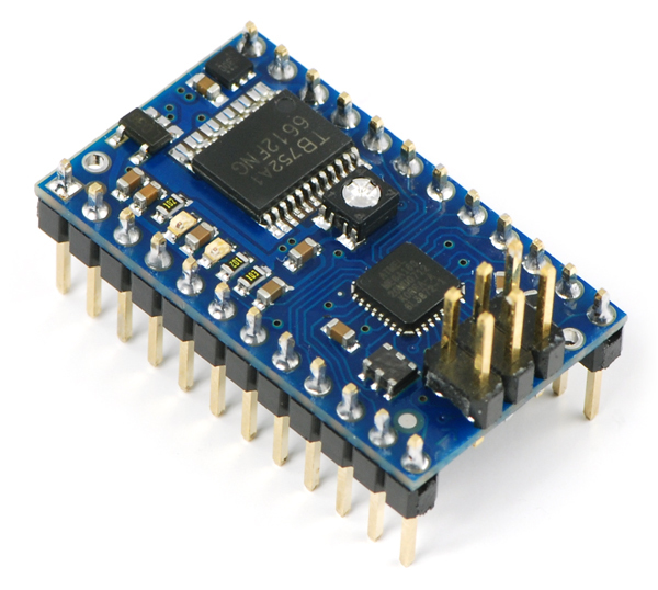
Here is an example of what nice solder joints should look like:
–David