JRK 12v12 Problem - No Motor movement

Hello from germany!

I bought a Polulu JRK 12v12 to run a linear actuator which is similar to that, which is selling here. (Link of my linear actuator is here: http://www.conrad.biz/ce/de/product/191745/Transmotec-DC-Linear-Motor-DLA-DLA-12-40-A-100-POT-IP65-16024244CR-12-VDC-Hub-Laenge-100-mm-Schubleistung-1200-N-Geschwi/1101104&ref=list
This is the same actuator but with a different gearbox (40:1) to have more force.

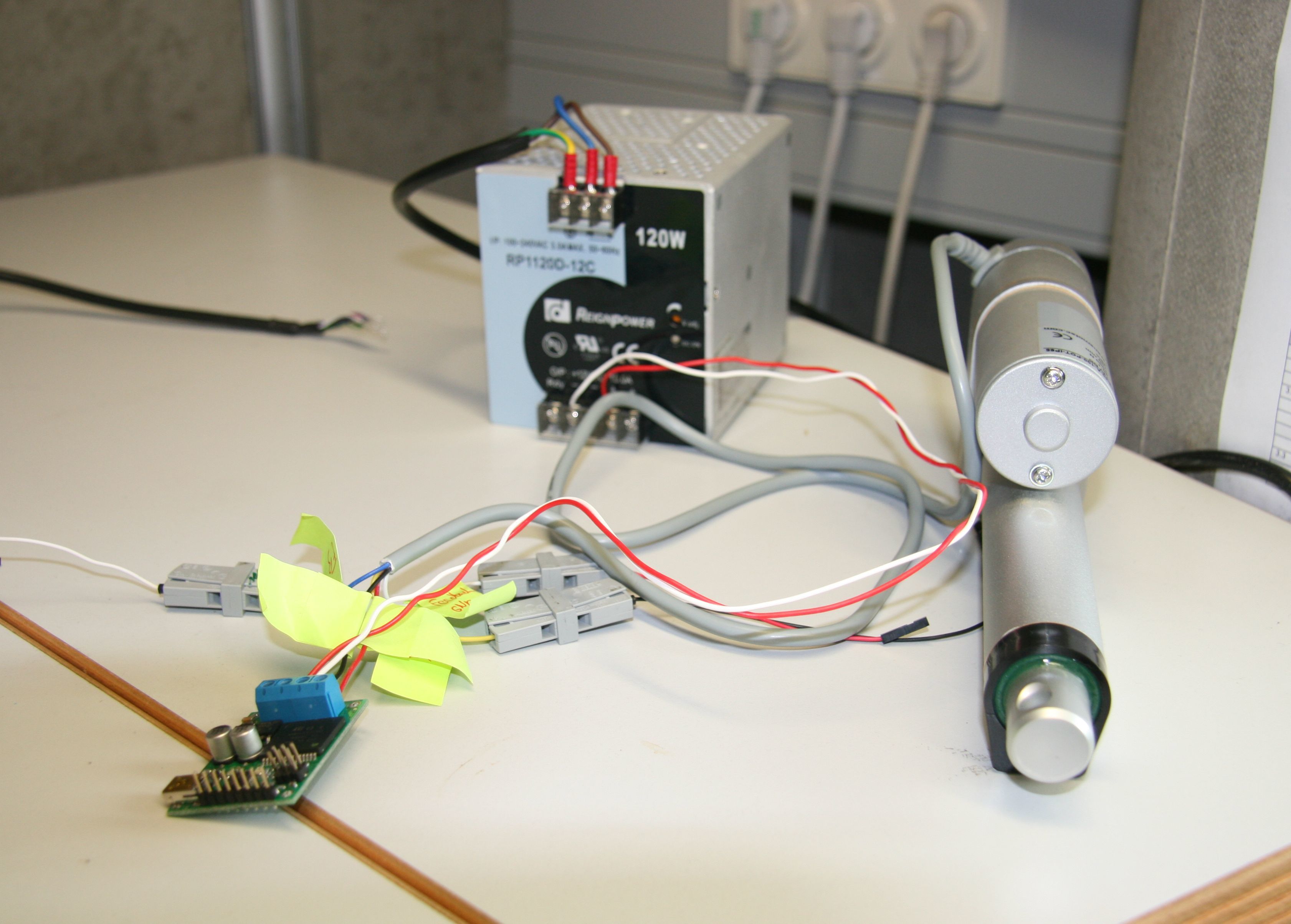
My powersupply is a 120 W 12V 10A supply from industry. It dropes the need 12v without a problem.

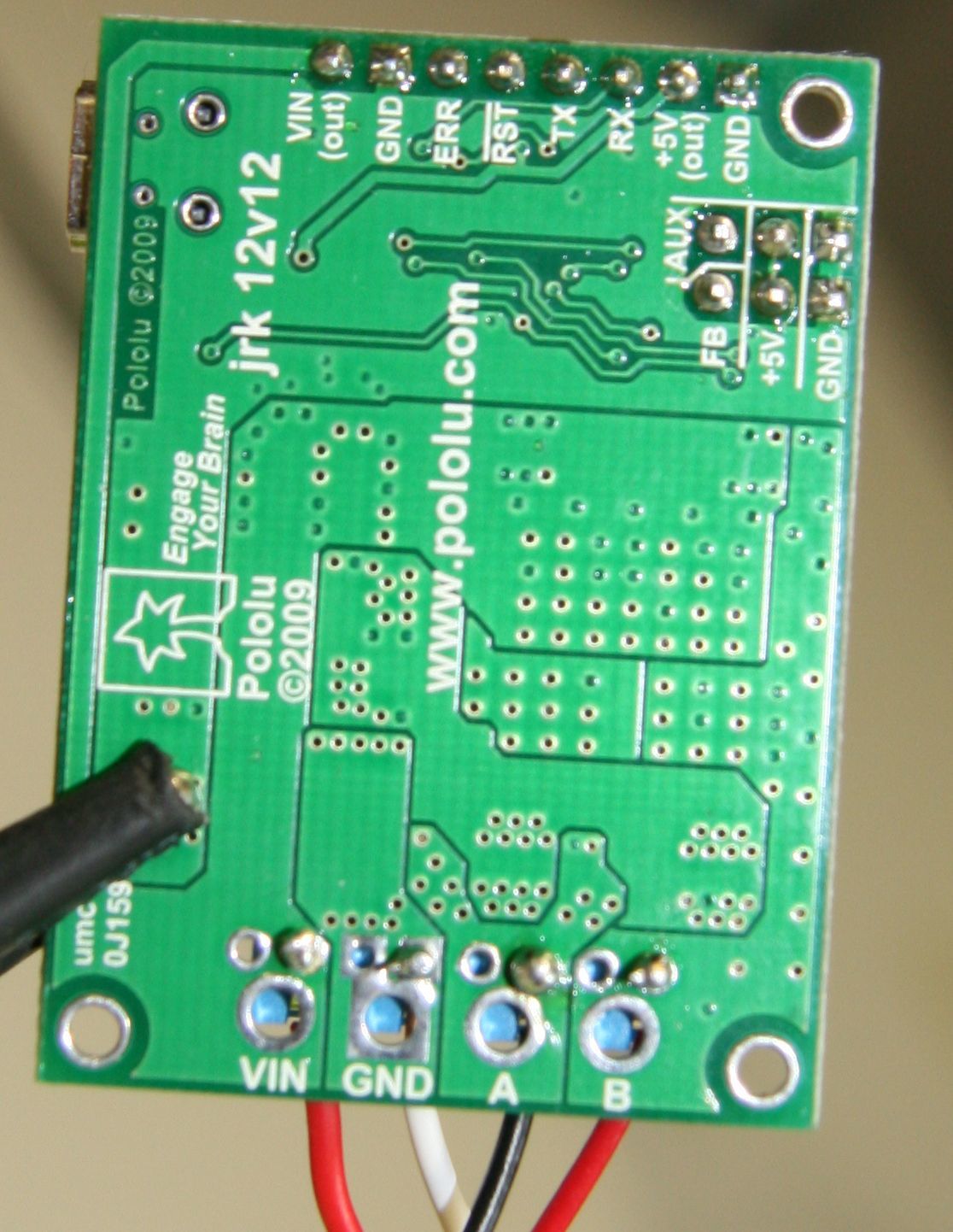
I wired plus and minus from my power supply to the JRK (VIN, GND). From the actuator i wired the black (gnd) and red (+) cable to a and b (the same as in your picture discription on LA product pages). i measured the VIN and GND voltage drop, and its 12v. Feedback is also connected.

In the configuration utility, i load the start settings as described in the product guide for the jrk. i applied every settings using the apply button. i deactivated feedback, i use serial mode with USB Dual Port.

Motorsettings: everything as default, but limited the max current to 4 A to test.

THE PROBLEM:

When i press the “target” button or the “run motor” button, nothing happends. The motor wont drive.
During the “run motor” command, the error status shows: 0x0000 and in the error tab nothing is shown.
When i clicked “stop motor” then i got an error: 0x0001. I think this is okay, because its the bit to stop the motor?

several times i got errors on 0x0002 and 0x0004. But normaly not!

When the motor should be running (when button is pressed) i measured the voltage dropdown. Voltage is only 0,4V!
What happens here? What can i do to move the actuator.

i ordered the not assembley version of the jrk, so i soldered the screw terminals and pins on my self. but they are also contacted i think. could the problem be there?

I tried to connect the actuatur directly to the power supply, everything is ok. The actuatur moves.

Thank you for helping me. I can make pictures if this helps.

Hello.

What is the jrk’s Feedback Mode set to? What is the Input Mode set to? What did you set the target to? If you just want to get it running without feedback, you should set it to Feedback Mode = None, Input Mode = Serial, and set the target to 2648.

–David

Hello David,

thanks for your answer.

I set Feedback mode to "none"
Input Mode to Serial (USB Dual)
and set the target to 2648, nothing happend :frowning:
exactly the same problem as i described in my previous post, any idea?

Did you remember to press the “Set Target” button? What value for the Target is displayed in the upper-left corner of the window? Could you save a jrk settings file (from the File menu) and post it here so I can see all of your settings?

–David

Hey David,

ich pressed the set target button when i entered 2648. The Target displays: 2648. Nothing happens.

I tested the whole system on two computers. Something is wrong.

Here is the configuration file:

INITIALIZED 0
INPUT_MODE SERIAL
INPUT_MINIMUM 0
INPUT_MAXIMUM 4095
OUTPUT_MINIMUM 0
OUTPUT_NEUTRAL 2048
OUTPUT_MAXIMUM 4095
INPUT_INVERT 0
INPUT_SCALING_DEGREE 0
INPUT_POWER_WITH_AUX 0
INPUT_ANALOG_SAMPLES_EXPONENT 5
INPUT_DISCONNECT_MINIMUM 0
INPUT_DISCONNECT_MAXIMUM 4095
INPUT_NEUTRAL_MAXIMUM 2048
INPUT_NEUTRAL_MINIMUM 2048
SERIAL_MODE USB_DUAL_PORT
SERIAL_FIXED_BAUD_RATE 9600
SERIAL_TIMEOUT 0
SERIAL_ENABLE_CRC 0
SERIAL_NEVER_SUSPEND 0
SERIAL_DEVICE_NUMBER 11
FEEDBACK_MODE NONE
FEEDBACK_MINIMUM 0
FEEDBACK_MAXIMUM 4095
FEEDBACK_INVERT 0
FEEDBACK_POWER_WITH_AUX 0
FEEDBACK_DEAD_ZONE 0
FEEDBACK_ANALOG_SAMPLES_EXPONENT 5
FEEDBACK_DISCONNECT_MINIMUM 0
FEEDBACK_DISCONNECT_MAXIMUM 4095
PROPORTIONAL_MULTIPLIER 0
PROPORTIONAL_EXPONENT 0
INTEGRAL_MULTIPLIER 0
INTEGRAL_EXPONENT 0
DERIVATIVE_MULTIPLIER 0
DERIVATIVE_EXPONENT 0
PID_PERIOD 10
PID_INTEGRAL_LIMIT 1000
PID_RESET_INTEGRAL 0
MOTOR_PWM_FREQUENCY 0
MOTOR_INVERT 0
MOTOR_MAX_DUTY_CYCLE_WHILE_FEEDBACK_OUT_OF_RANGE 600
MOTOR_MAX_ACCELERATION_FORWARD 600
MOTOR_MAX_ACCELERATION_REVERSE 600
MOTOR_MAX_DUTY_CYCLE_FORWARD 600
MOTOR_MAX_DUTY_CYCLE_REVERSE 600
MOTOR_MAX_CURRENT_FORWARD 67
MOTOR_MAX_CURRENT_REVERSE 67
MOTOR_CURRENT_CALIBRATION_FORWARD 149
MOTOR_CURRENT_CALIBRATION_REVERSE 149
MOTOR_BRAKE_DURATION_FORWARD 0
MOTOR_BRAKE_DURATION_REVERSE 0
MOTOR_COAST_WHEN_OFF 0
ERROR_ENABLE 126
ERROR_LATCH 126

Yes, it sounds like something is wrong. Just to make sure, could you post a clear, in-focus picture showing your soldering of the screw terminals? You can upload the picture as an attachment here.

–David

Hey David, here is the picture from my soldering.


By the way, for the benefit of anyone reading this and in case you get another jrk 12v12, the screw terminals are meant to be soldered into the larger holes, not the smaller ones as shown above. The way you soldered it will work though.

It’s hard to tell because of the angle, but all of your power and motor connections look suspect to me, especially the connection for A where it looks like there is a big ball of solder above the hole. The jrk does not report a problem with the VIN power, so those connections probably are sufficient. However, for the VIN connection it does look like half of the hole is missing solder. The power and motor connections are harder to solder than the logic connections, because the pads are connected to large copper areas. As a result it is easy for solder to wet to the pin without wetting to the pad because the pad isn’t getting hot enough.

There are a couple quick tests you can do to see if the soldering is the problem:

With a multimeter, you could measure the resistance between the metal rim of the large holes and the corresponding contacts of the screw terminal block where you plugged in your motor wire. If the soldering is good, it should be close to 0 Ohms.

You could unscrew the two motor leads from the A and B screw terminals, turn the jrk upside down and use your fingers to hold the motors leads against the large holes labeled A and B. While you are doing this, see if the jrk can drive the motor. Make sure to try both directions (target = 2648, target = 1448) just in case the actuator has reached the end of its range of motion.

Here is an example of what nice solder joints should look like:

–David

Hey David, that was the problem! I measured the soldering pads and there were ~10 Ohm on Motor A and VIN. I resoldered the pad and now it runs :slight_smile:
Thanks for your help!