Jrk 12v12 = disappointment? usb connection problems

Hello dear forum,

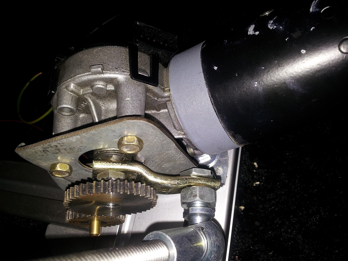
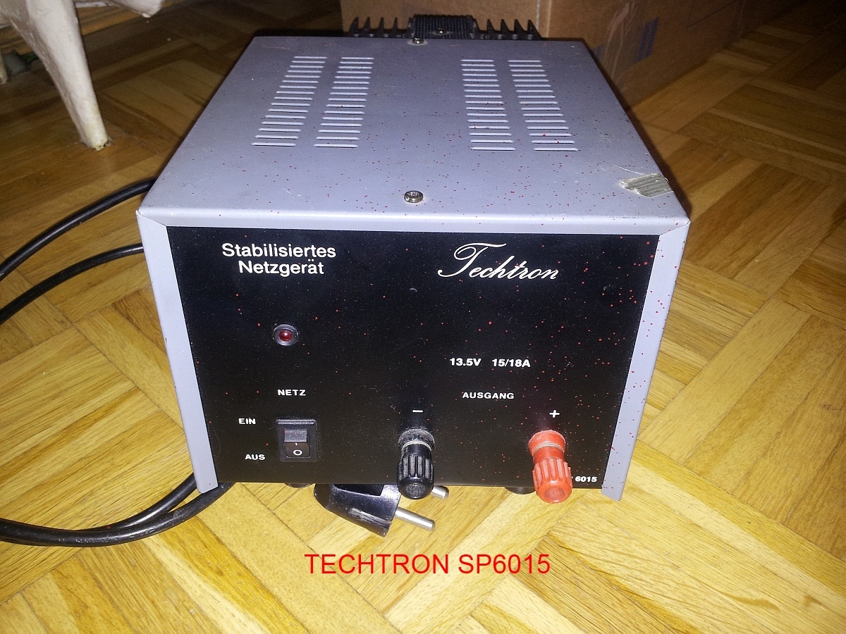
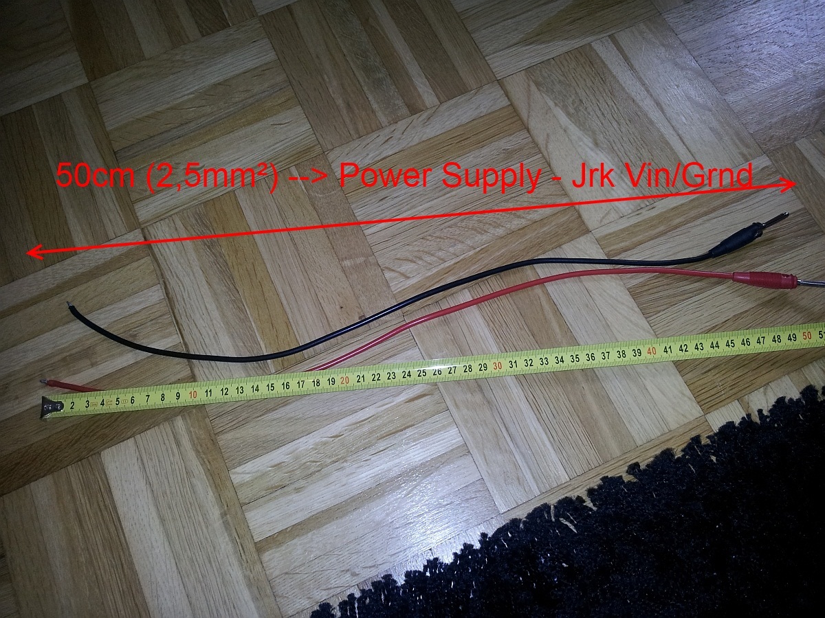
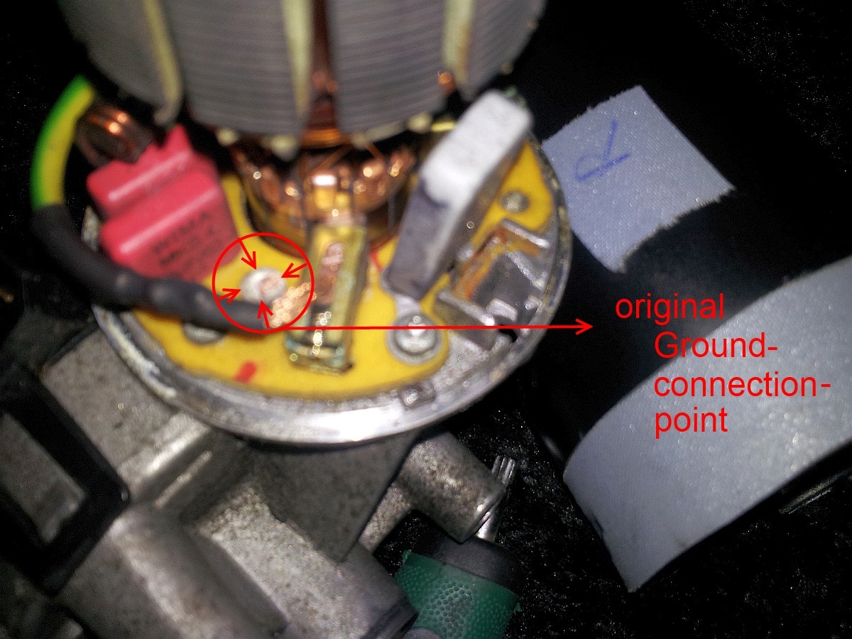
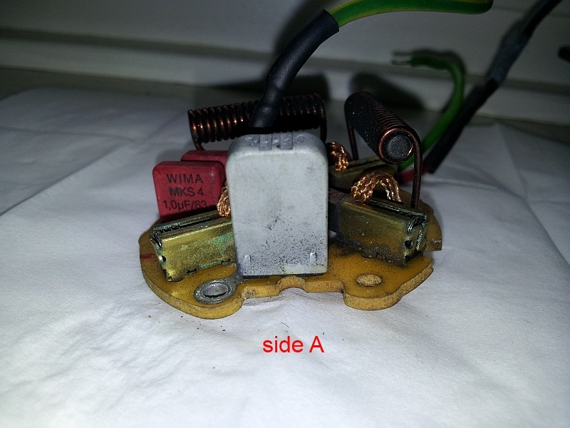
I build a Motion-Sim "http://www.x-sim.de/forum/viewtopic.php?f=3&t=268&p=1548#p1548. Using 2x Jrk 12v12; 2x wipermotor Vw Golf (ground wire soldered to the brush - so no bodyground like original); Techtron SP6015 Powersupply (13,8V 15-18A); 2x Potentiometer 10kohm - they are attached via gearing to the wipermotors for feedback. Win7 32bit, also tried Xp SP3 32bit and Win7 64bit with differnet usb-cables.

All connected like said in the manual - also the configuration utility (and driver) is installed like recommended.

On first test’s everything worked so far and i could set target via configuration utility. On the other day when i wanted to test i bit more one of the two boards was not recognized via usb. The green led blinked short after connecting - after that all lights off. I tried this on all usb-ports and different pc. I tried to connect ground and reset but nothing happens (vin, ground, motor, poti connected). There is no notification by windows if pluged in! Even in device manager no unknown device?

Ok so far very frustating espacially because i want to use my now machanically ready sim so badly :slight_smile:

This testing with the board took me two days after work until i gave up. Found nothing similar on googel.

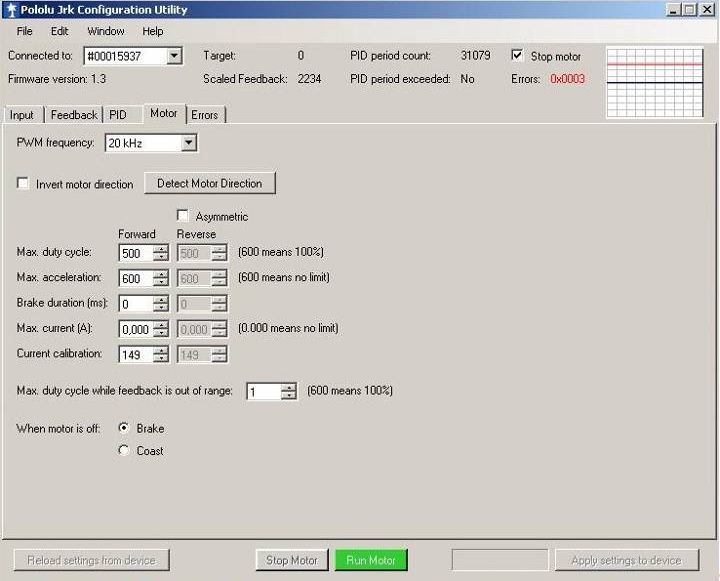
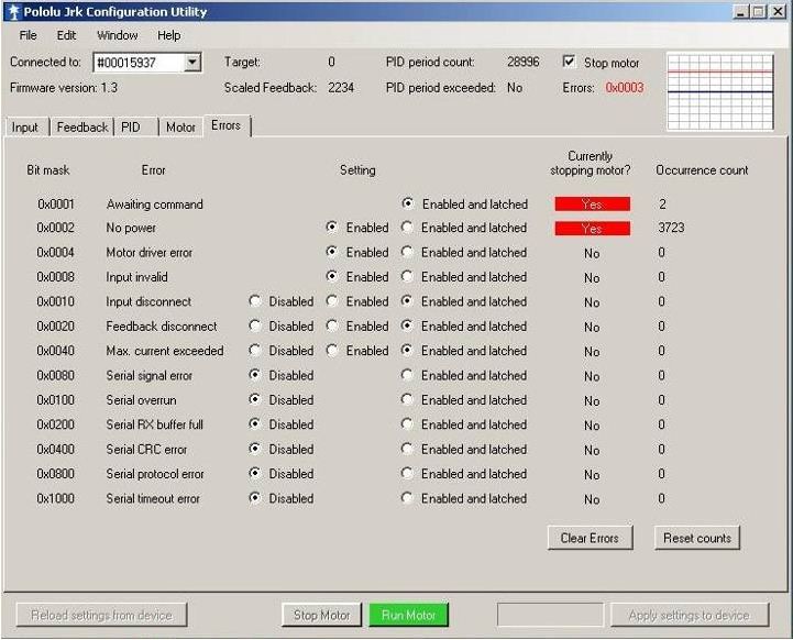
After that issiue i started to test with the working board and ordered one for safety/replacement for the other. I could not believe that this board is stressing now to. Here some screenshot’s and the error text:


error: "Informationen über das Aufrufen von JIT-Debuggen
anstelle dieses Dialogfelds finden Sie am Ende dieser Meldung.

************** Ausnahmetext **************
System.Exception: There was an error turning off the motor. ---> System.ComponentModel.Win32Exception: Control transfer failed.
   bei Pololu.WinusbHelper.WinUsbDevice.controlTransfer(WINUSB_SETUP_PACKET setupPacket, Byte* buffer)
   bei Pololu.WinusbHelper.WinUsbDevice.controlTransfer(WINUSB_SETUP_PACKET setupPacket)
   bei Pololu.UsbWrapper.UsbDevice.MyWinUsbDevice.controlTransfer(Byte RequestType, Byte Request, UInt16 Value, UInt16 Index)
   bei Pololu.UsbWrapper.UsbDevice.controlTransfer(Byte RequestType, Byte Request, UInt16 Value, UInt16 Index)
   bei Pololu.Jrk.Jrk.motorOff()
   --- Ende der internen Ausnahmestapelüberwachung ---
   bei Pololu.Jrk.Jrk.motorOff()
   bei Pololu.Jrk.MainWindow.setMotorState(Boolean motorOn)
   bei Pololu.Jrk.MainWindow.motorOffButton_Click(Object sender, EventArgs e)
   bei System.Windows.Forms.Control.OnClick(EventArgs e)
   bei System.Windows.Forms.Button.OnClick(EventArgs e)
   bei System.Windows.Forms.Button.OnMouseUp(MouseEventArgs mevent)
   bei System.Windows.Forms.Control.WmMouseUp(Message& m, MouseButtons button, Int32 clicks)
   bei System.Windows.Forms.Control.WndProc(Message& m)
   bei System.Windows.Forms.ButtonBase.WndProc(Message& m)
   bei System.Windows.Forms.Button.WndProc(Message& m)
   bei System.Windows.Forms.Control.ControlNativeWindow.OnMessage(Message& m)
   bei System.Windows.Forms.Control.ControlNativeWindow.WndProc(Message& m)
   bei System.Windows.Forms.NativeWindow.Callback(IntPtr hWnd, Int32 msg, IntPtr wparam, IntPtr lparam)


************** Geladene Assemblys **************
mscorlib
    Assembly-Version: 2.0.0.0.
    Win32-Version: 2.0.50727.5456 (Win7SP1GDR.050727-5400).
    CodeBase: file:///C:/Windows/Microsoft.NET/Framework/v2.0.50727/mscorlib.dll.
----------------------------------------
JrkConfigurationUtility
    Assembly-Version: 1.2.1.0.
    Win32-Version: 1.2.1.0.
    CodeBase: file:///C:/Program%20Files/Pololu/Jrk/bin/JrkConfigurationUtility.exe.
----------------------------------------
System.Windows.Forms
    Assembly-Version: 2.0.0.0.
    Win32-Version: 2.0.50727.5460 (Win7SP1GDR.050727-5400).
    CodeBase: file:///C:/Windows/assembly/GAC_MSIL/System.Windows.Forms/2.0.0.0__b77a5c561934e089/System.Windows.Forms.dll.
----------------------------------------
System
    Assembly-Version: 2.0.0.0.
    Win32-Version: 2.0.50727.5456 (Win7SP1GDR.050727-5400).
    CodeBase: file:///C:/Windows/assembly/GAC_MSIL/System/2.0.0.0__b77a5c561934e089/System.dll.
----------------------------------------
System.Drawing
    Assembly-Version: 2.0.0.0.
    Win32-Version: 2.0.50727.5462 (Win7SP1GDR.050727-5400).
    CodeBase: file:///C:/Windows/assembly/GAC_MSIL/System.Drawing/2.0.0.0__b03f5f7f11d50a3a/System.Drawing.dll.
----------------------------------------
Jrk
    Assembly-Version: 1.1.0.0.
    Win32-Version: 1.1.0.0.
    CodeBase: file:///C:/Program%20Files/Pololu/Jrk/bin/Jrk.DLL.
----------------------------------------
System.Windows.Forms.resources
    Assembly-Version: 2.0.0.0.
    Win32-Version: 2.0.50727.5420 (Win7SP1.050727-5400).
    CodeBase: file:///C:/Windows/assembly/GAC_MSIL/System.Windows.Forms.resources/2.0.0.0_de_b77a5c561934e089/System.Windows.Forms.resources.dll.
----------------------------------------
UsbWrapper
    Assembly-Version: 1.1.0.0.
    Win32-Version: 1.1.0.0.
    CodeBase: file:///C:/Program%20Files/Pololu/Jrk/bin/UsbWrapper.DLL.
----------------------------------------
mscorlib.resources
    Assembly-Version: 2.0.0.0.
    Win32-Version: 2.0.50727.5456 (Win7SP1GDR.050727-5400).
    CodeBase: file:///C:/Windows/Microsoft.NET/Framework/v2.0.50727/mscorlib.dll.
----------------------------------------

************** JIT-Debuggen **************
Um das JIT-Debuggen (Just-In-Time) zu aktivieren, muss in der
Konfigurationsdatei der Anwendung oder des Computers
(machine.config) der jitDebugging-Wert im Abschnitt system.windows.forms festgelegt werden.
Die Anwendung muss mit aktiviertem Debuggen kompiliert werden.

Zum Beispiel:

<configuration>
    <system.windows.forms jitDebugging="true" />
</configuration>

Wenn das JIT-Debuggen aktiviert ist, werden alle nicht behandelten
Ausnahmen an den JIT-Debugger gesendet, der auf dem
Computer registriert ist, und nicht in diesem Dialogfeld behandelt."

This board is not every time recognized via usb. When it is then it is listed in device manager. In configuration utility i can do nothing - there is even no firmware number shown.

Don’t know what to do - I sended the boards back so someone “professional” can have a look. I really like the configuration and the boards are good to use with x-sim and uso commands. Please let me know where my mistake could be? Support was contacted previous.

Regards yoko

Not recognized:
http://www.abload.de/image.php?img=pololu_1o9rdi.jpg
http://www.abload.de/image.php?img=ploluxjqn7.jpg

Recognized:
http://www.abload.de/image.php?img=pololu_64jo5l.jpg
http://www.abload.de/image.php?img=pololu_37povf.jpg
http://www.abload.de/image.php?img=pololu_4iiowq.jpg
http://www.abload.de/image.php?img=pololu_5usonm.jpg

sry image does not work with my links in prev post…?

Firmware update does not work too - can’t select a comport (even if they are in devicemanager).

Regards

Hello, yoko.

I am sorry you are having trouble with the jrk 12v12.

If you give us more information about your setup, we might be able to offer some advice. Could you post some good photos of your setup showing your connections, power supply, and motor? What type of power supply are you using? What type of motor are you using? How long are the leads from the power supply to the jrk? How long are the leads from the jrk to the motor? What settings did you edit in the jrk configuration utility?

The 0x1F error you are seeing is a general failure error code from Windows, which can be caused by many different things. For you, I think it’s probably caused by electrical noise from the motors that interferes with the USB port and causes it to shut down. If nothing else works, you might try using a USB opto-isolator.

The BBCode [img ] tag expects you to give the URL of an image, but the urls you supplied were actually for HTML web pages (even though they ended in .jpg). This is the kind of URL you can put inside an img tag: abload.de/img/pololu_64jo5l.jpg

Here’s an example of it working:

–David

Hi David,

thank you for your fast answer. I will post my setup with some quality detail pics later this eveing or tomorow. Tank you so far.

Ps.: I got this problems also without motors attached to the jrk. What also suprises me - other user’s of the x-sim forum have equal configurations running. They said i should use the jrk (before i wanted to use sabbertooth + k8055).

Regards yoko

Hello David,

here some detail’s of my setup. Sorry for the bad pic quality - I think I need a real cam soon :blush:


This is all about… My goal is to use this as a simulator for racing games like “rfactor” or “gtr2”. It’s build of bosch aluminium profiles. There are two frames. One is attached to the seat the other is the base. The both frames are connected by a rubber-bonded metal “bearing” with 55shore exactly in center of gravity. To restrict the degrees of freedom i used two rod’s connected to the seat- and baseframe. The sim has two degree’s of freedom so far (to simulate braking; acceleration and cornering l/r + curbs…). In my Catia Simulation I got another dof ready for traction loss but one step after the other.
The movement of the seat is made by two wipermotor’s of a Volkswagen Golf. The leverage arm length is 4,5cm. The rotation 120° for first test’s. When somebody is sitting in the seat there is no “heavy” force needed to move it (because of center of gravity) - i can move the seat with my little finger (can’t say exact [N]).


I use 10kohm Potentiometers with 300° for feedback. They are attached to the motor via gearwheels (gear ration 1/1,6).
Thats about the mechanic part - if I missed something important pls ask.


This is my power-supply. Techtron SP6015 - 13,5V 15-18A. Both Jrk are connected to this, hope it is strong enough. (I reduced the motors in configuration utility by 5A each).


The wires are 4x 50cm - 2,5mm² from Jrk Vin/Grnd to Power supply. For the motors I use 30cm 1,5mm² to connect to the Jrk.

Because of sending back the two Jrk’s for checking I just can send you a schema of connection:


The motor are modified this way.
Normally the ground “is on the case” of the motor. Volkswagen car’s have their chassis/body as ground (like nearly all other). I soldered the wire direct to the brush that is normally connected to case (see pic).
The wiper got 2 speed’s. I use the faster one (timing of the brush is differnet) - with the “red” wire.

For all soldering job’s I used a “Weller WSD81” and “Mundorf Msolder silver”.

In the configuration utility I used the following settings:


And the configuration for the Jrk’s in x-sim software:

This programm uses the data of the game and send’s the command to move left or right motor.

Ok. I hope you can understand me correct - as not nativ speaker ti’s really hard to explane sometimes. If I missed something important please ask.

Best regards
yoko

PID: 1/0 0/3 0/0 ; PID period =10ms

ps.: what is max resolution that pic’s are not cutted?

edit: by rightclick “schow image” you can see full pictures…

Thank you for all those pictures! I was able to see the full images because my monitor is wide enough, but if you are worried about them getting cut off then it is a good idea to limit the width to about 800 pixels. There seems to be no hard limit; whether or not it gets clipped just depends on how wide the reader’s browser window is.

It sounds like you haven’t tuned your PID parameters. The system will probably perform better if you follow the PID tuning instructions in the “Setting Up Your System” section of the jrk user’s guide when you get the chance, but I don’t know if that will fix the main problem.

Another thing that could help is to set an acceleration limit in the jrk configuration utility, to prevent the motor from drawing too much current too fast.

I see your motors already have capacitors on them, but maybe it would be useful to add more. We some information about that in the “Dealing with Motor Noise” section of this application note.

I don’t see anything particularly wrong with your setup, but those are some suggestions that might help.

Do you know the stall current of those motors? In other words, how much current do they draw when starting up?

–David

Hi David,

tank you for the links. I will read them this evening. Hope this will help me with my Usb-problem’s.

For the weekend I invited a friend who will bring his Fluke Oszilloskop. I studied engineering (focus car) but in germany is unfortunately no duty for advanced electronic readings. So I don’t selected them :confused:
Wrong decision…
My friend is much more related to this stuff. I will let him read this thread and perhaps additional 2 eyes will be good. To my mind I checked everything 50 times. Everthing is connected fine. With a normal multimeter there are no “ground” or “potential” issiues on the motorcase, frame, Poti. I just haven’t measured the current [A], because my Multimeter is veary cheap and I don’t think it’s approved for this.

You are right - there is no limit in the screenshot but while I tested the boards I reduced the current to 5A per motor. I don’t think this could be wrong. I don’t know the exact current of the motor. But in my opinion under load there will be much more “A” than 5A. When the Sim is ready it will be used for 2-3 hours without pause. I ordered some fans 2x 40x40mm for the boards (also got 14x14x6mm heatsinks) and 2x 120x120mm for the motor (with baffle plates). Because of this points I wanted to start with the 5A. If the temperatures will stay in realistic areas I wanted to raise the current by 1A per motor and test again.
Am I right - if my power supply is reputed to can do 15-18A - can I go with the 2 Jrk’s and 7,5-9A on it? :question: Even at the 5A the motors felt very strong while playing with “set value” (when everything eas working :imp: ).

For PID - did I change something bad? I admit i read the part on the manual but with my english skills I really don’t understand nothing. So I googel on x-simulator forum and a user with great working sim (nearly same electric setup) used this PID. Another tipp of PID was " PID of 2/2 0/3 1/1 ". Would this be better? I promise I will read the PID manual part again and ask my questions on it here if it’s ok?

Any suggestions for the USB behaviour?

Best regards
yoko

Hi,

I disassembled one motor again and removed the “board” with the brushes and co. Did not expect this:


Top


Side view


Bottom !

Do the capacitators work this way. I think I need to connect the “old” brushconnection point with the copperpoint. The red part’s got just one potential so, or?
What does that grey thing do, no identification on it? :unamused:

Thanks.

Hi David,

thanks for the great link on electric noize!!!
I wanted to look after this what shall I order - are the items in the artivel ok for my application/motors? Or should I use other Capacitor’s?

I need 6x 0.1 μF 50 V ceramic capacitors for two motor’s, correct? Can you send me an idiot-safe illustration how to solder them at my motors? In the pic of the articel there are two to case and one “wire” and one across. But I think my case should be potential and ground free?

I will also need 2 or 4x 330 uF, 35 V radial electrolytic capacitor for be safe, correct? They are attached to Vin/Gnd on Jrk - can they also be attached on A/B?

Ps.:sorry for so many post after another…

Best regards
yoko

New progress,

may you take a look at this:


The grey part and the third brush a removed completly.

I changed the “board” of the brushes. There are now the original 1,0µF 63V capacitors connected to case and to brush (pro brush). Also there is a coil from wiring to brush (pro brush). When I add a third capacitator between the brushes (as short as possible) what dimension should I go? Is the dimension for the two ok? I used them because of originally used in this motor.


Are ferrit cores for the wires to the brushes (as near to the brush as possible or as near to jrk’s as p.) recommended? I read on a german website about.

You asked about stall current of the motor. It’s really hard to get any information on this. The sources are not good often!
Voltage in a car with running alternator is about 13,5V. For power I often read something about 30-40W. The stall current changes dpending on source between 10->25A…?
The only official I found (but not!!! my motor, just a analog typ):

Perhaps this help?
Please could someone commentate on this and my previous questions? I ordered two seperat Jrk’s and they will come tomorrow. I don’t want to test again before I get an official “gogogo”. :wink:

Another question: Is it safe to use a car batterie (12V 45Ah 360A) parallel to the power supply (to help the power supply a bit with peak current)?

Best regards
yoko

Hello.

Generally, putting two power supplies in parallel is difficult to do properly and I would not recommend it.

I don’t understand your comment about the current. What do you expect the stall current of this motor to be at the voltage you are using? I am worried that this motor might be too beefy/large for the jrk to handle, and draw too much current. Maybe you could compare it to the motors that other x-sim users have.

You could try setting a Max Duty Cycle limit in the jrk configuration utility, to slow down the motor and avoid drawing too much current. As a first step I would try setting it to 100 (out of 600).

–David

Mhhh the other users use the same motors (just of other brands but Wiper’s are very common). There are even users with alot bigger boatwinch-motors or wheelchairmotors using the jrk with x-sim.

I searched alot on the web but I got no real informations. I don’t really know the stall current of the motor. Some forum people say 10A some say 25A - I don’ know. It will be best to wait till weekend - and measure it with a current clamp and oszilloskop.

Best regards
yoko