
Hello,
I’m fairly new to electronics and I’ve run into an issue with using the Pololu G2 High-Power Motor Driver 18v17 for a small tracked robot I’m trying to build and control. The goal is to be able to control the robot using an RC transmitter and make it move forward, backward, turn, etc.
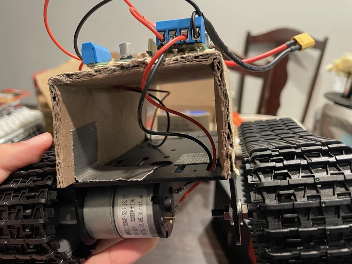
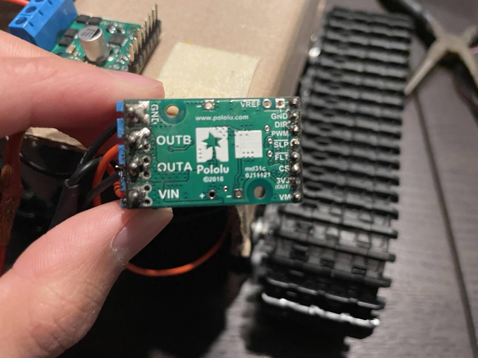
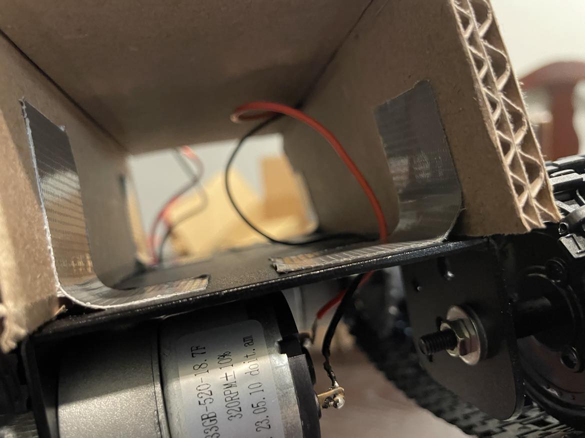
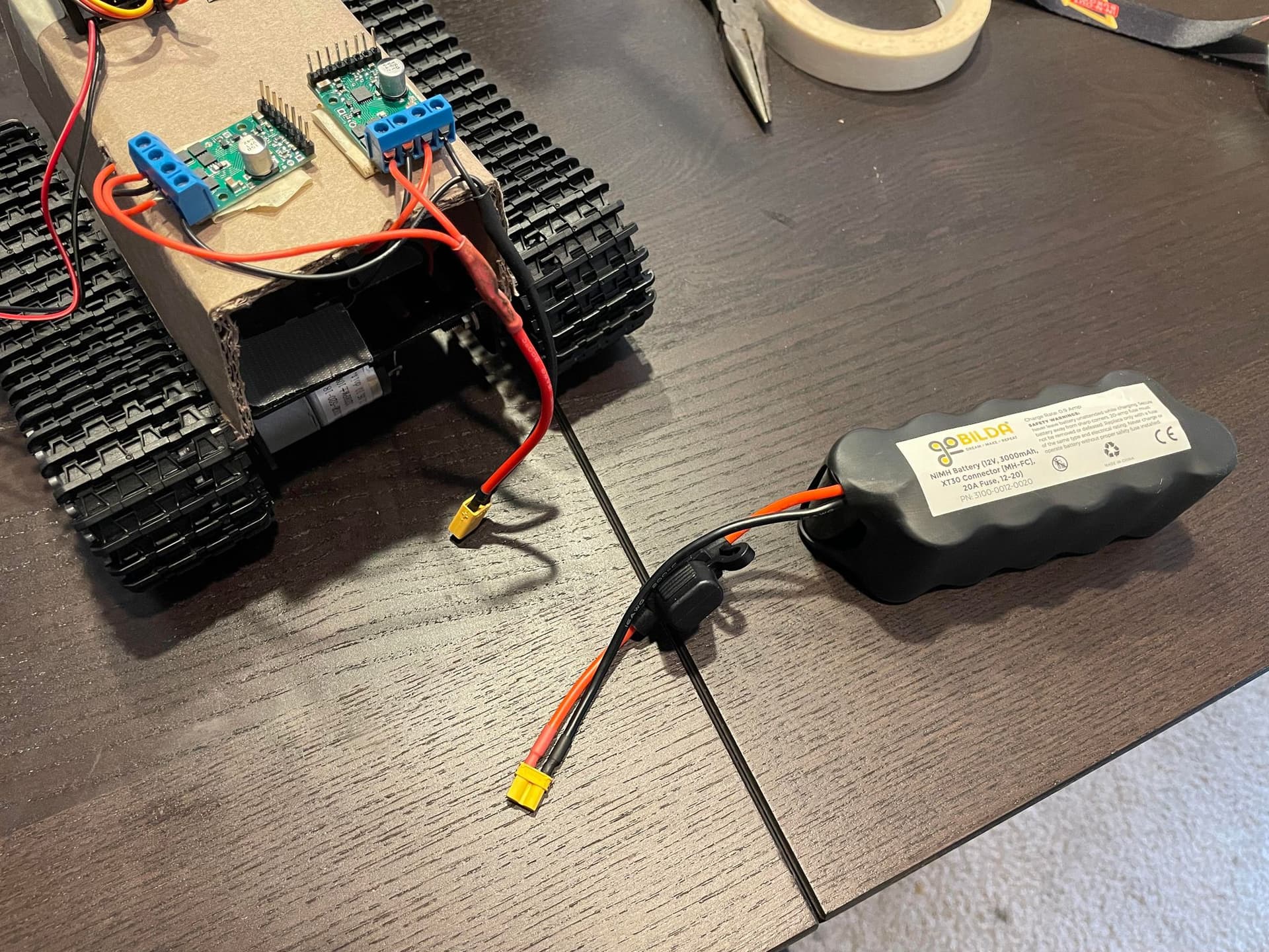
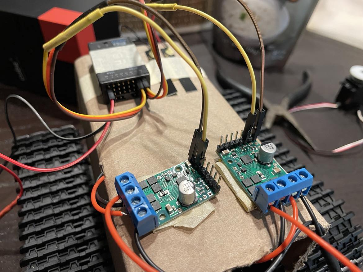
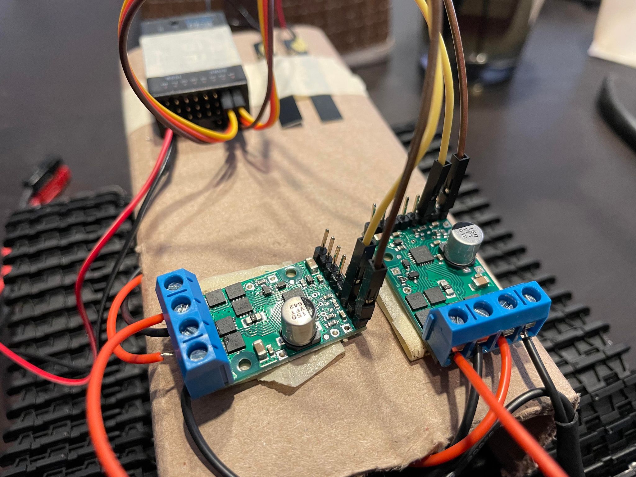
The motors on the robot and the motor drivers are connected as follows: The motor driver on the right hand side (as oriented in the pictures below) is connected to the front motor of the robot, which drives the left side wheels. The motor driver on the left hand side is connected to the rear motor of the robot by feeding the wires through a small hole in the cardboard shield (below), driving the right side wheels. Both motor drivers are wired from OUTA and OUTB on the boards to the two terminals of their respective motors. For reference, I have attached the solders on the rear side of both boards as well.
Right hand side motor driver:
Left hand side motor driver:
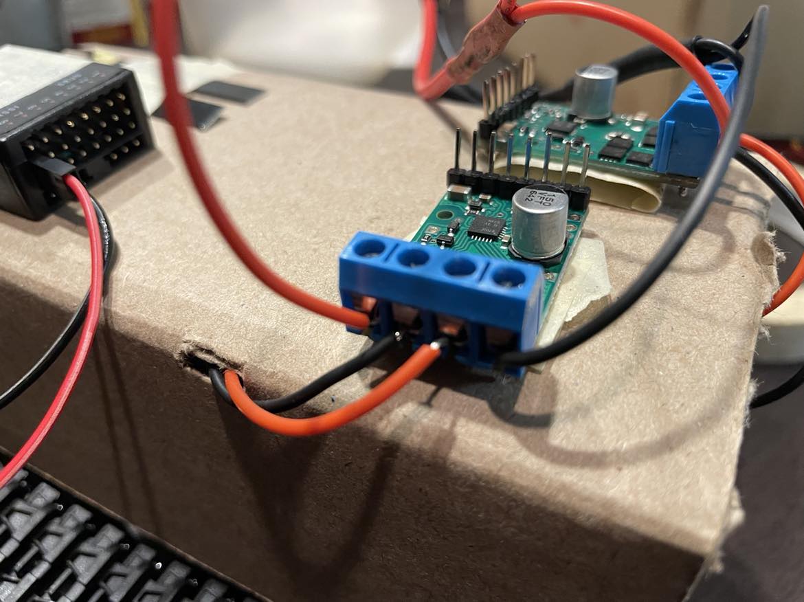
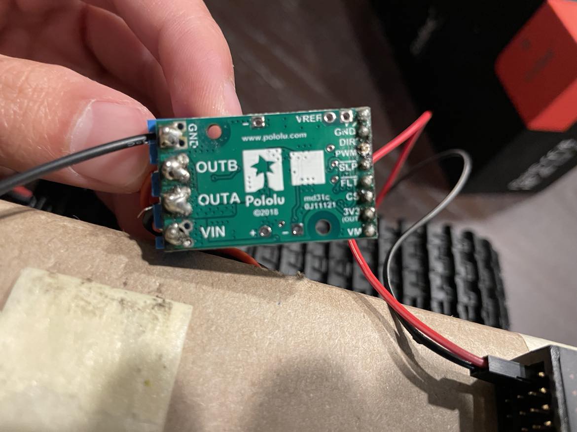
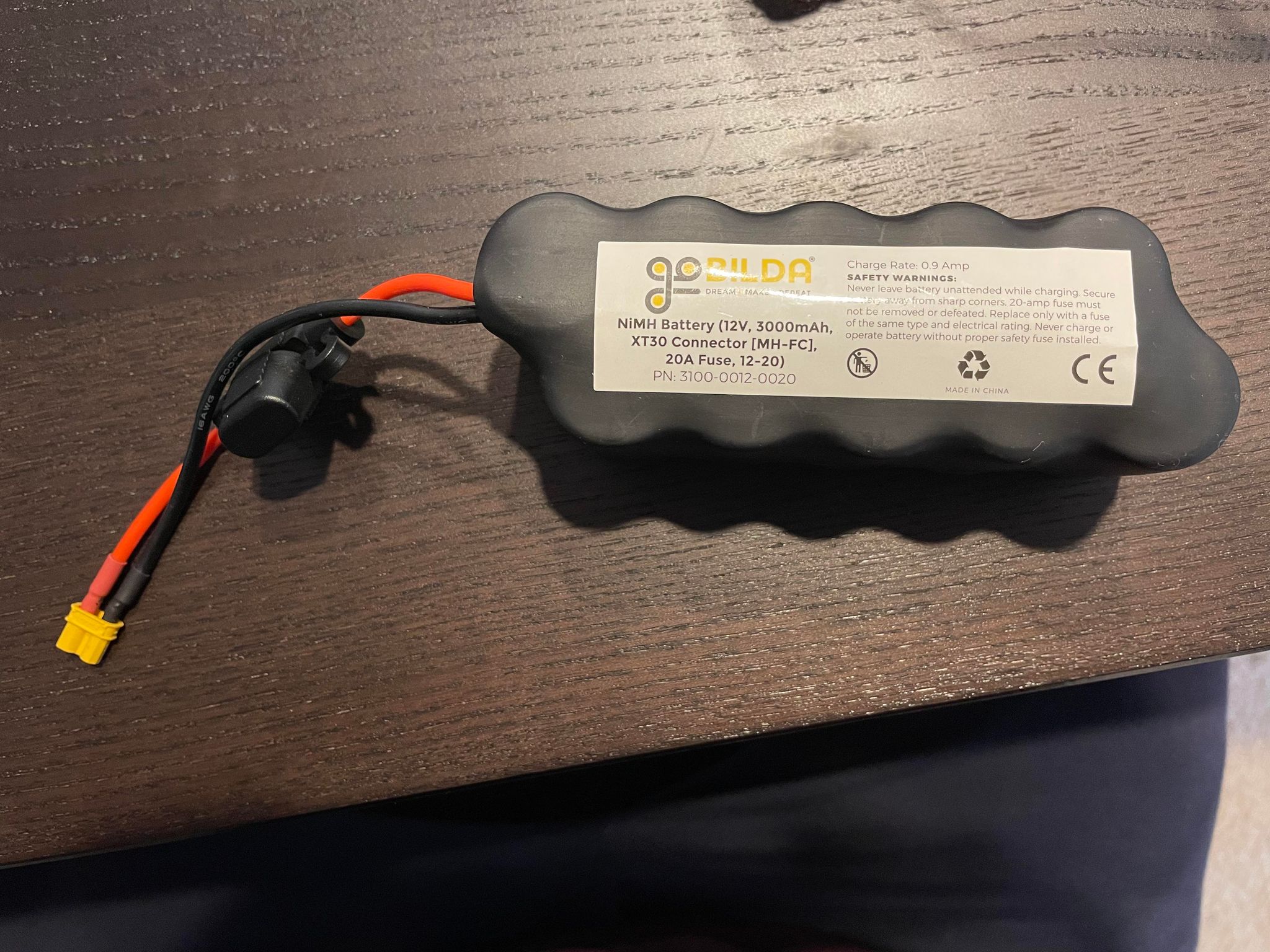
The two red wires come out of the VIN terminals of the motor drivers and connect in parallel to the positive end of an XT30 connector; likewise for GND and negative. This plugs in to a 12V NiMH battery.
There are two questions I have / issues I’ve run into. First, when testing the motor drivers directly powered to the battery without any RC connections, only the right side wheels (connected to the left hand side motor driver) spin. Is there a reason for this? I also do not know if this behavior is normal, or if the motor should not be spinning when connected only to power. In other words, I do not know whether the motor driver that is stationary or the driver that is driving the motor is behaving properly.
The second, and more significant, issue that I have is that neither of the motor drivers seem to respond to RC controls. The RC transmitter I am using is an FrSky Taranis X9 Lite, and the receiver is an FrSky X8R. The X8R receiver operates between 4-10V and is powered by a 7.4V LiPo battery, connected to channel 8 of the receiver. When troubleshooting, I was able to confirm that the RC transmitter and receiver are working properly by using a servo motor. The servo, plugged into channel 1, responded to inputs on the Taranis transmitter.
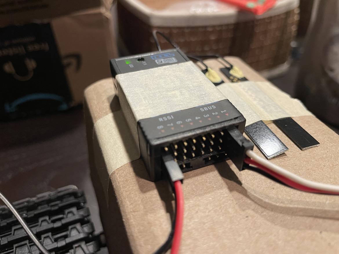
Swapping out the servo motor, I connected the motor drivers to channels 1 and 2 of the RC receiver. Since the receiver is already being powered by the external 7.4V battery, the red cables connecting to channels 1 and 2 are cut and unused. The yellow cable connects from the signal pin on the receiver to the motor driver’s PWM terminal, and the brown cable connects the receiver’s negative pin to the motor driver’s GND terminal. I should note, however, that I did initially have the wires connected to the wrong terminals on the left side board to CS and VM instead (I mistakenly got the board orientation wrong). When testing with this setup, both motors ran for a second or so, then there was a pop and some smoke, so it’s possible that the left side board is damaged.
In any case, following this, I fixed the RC wiring and tested once again. In the video clip below, I turned on the transmitter and receiver and set the transmitter inputs to near zero. I then expected the motors not to move when plugged into battery power, since their respective RC channels 1 and 2 were set to a signal value of zero on the transmitter. Instead, as soon as the battery power is connected to the motor drivers, both motors spin. Due to the previous troubleshooting, I am fairly confident that the transmitter and receiver are operating correctly, and thus the issue is somewhere in the motor drivers (either they aren’t operating as they should, or I’m missing some configuration), or the wiring to the drivers. At first, I thought the issue may have been caused by not utilizing the DIR terminal on the motor drivers, since I’m controlling the robot with RC rather than a microcontroller. However, I reviewed the driver specs which said that DIR is default set to Low, which I understand to mean that the drivers should still be operational and sending signal to the motors even without the DIR pin plugged in. How can I fix this issue so that the motors respond to the RC transmitter’s controls, like the servo motor does?
Thanks,
Amos