I recently order 2 of your motor drivers (24v12) and correctly received them (and my other stuffs, shipping was quick, thank you).
Unfortunately, I may be did something wrong with them as there are both faulty (but was working well firstly).
One has the PWM shorted to the ground and the other the DIR shorted to the ground (I did some tests in locked-anti-phase, may be it matters…)
During test, VCC was surrounding 25V (coming from two 12v batteries) and signals were generated from an ATMEGA 1280 (it correctly delivered 5V) and the 100 uF capacitor soldered between ‘+’ and ‘-‘.
Do you have any idea about what happened? What could I do to protect the controller?
Also, would it be possible to get a schematic ?
Did you change your setup between the time you verified they were working and the time they did not work? How do you know they aren’t working now? Is there any visible damage to them? Did you notice any smoke or noises when they broke? Is the setup you describe in your post the setup used when they stopped working? What PWM frequency were you using?
What was the load you were driving with the 24v12? Is it possible your load was wanting to draw more than 12 amps?
The setup was the same all the time. My first clue that something was wrong was when my mcu power down when I plugged it to the driver. Ohmmeter said 2 Ohms between shorted pins and GND.
I removed headers and the capacitor and did not notice any visible damage. Neither noise nor smoke.
The frequency during tests was 20Hz (I know that too slow and changed that to 20kHz).
Moreover I managed to drive a motor using the controller with DIR shorted to the ground (I did not connect the pin) and that was working well (but of course I was not able to change the direction).
The motor used during tests did not take more than 3/4 amps.
I am confused by your story. You talk about “tests.” Did your break while you were testing it? If it didn’t break while you were testing it, what was the difference between your non-test setup and your test setup. You say it broke when you connected the MCU. Did you have it running before you connected the MCU? This would mean there were at least 2 different setups (not the same setup the whole time).
Have you tried using the motor driver without the MCU? Can you verify that the driver is broken by isolating it from the rest of your electronics?
An MCU powerdown probably means you are having a power issue. Either your 5V supply is not providing enough current, or you have a wiring connection that is causing a short between your 5V and ground. What are you using as your 5V supply? A diagram or picture of your wire connections would be helpful in diagnosing the problem.
Ryan,
I am really sorry I was not clear and I realise I was maybe not right when I said [quote]The setup was the same all the time[/quote].
So yes, everything was working fine when I tested in lab with a waveform generator and power was coming from a power supply.
One week after, I tried again but with batteries and signals coming from MCU, and that was not working.
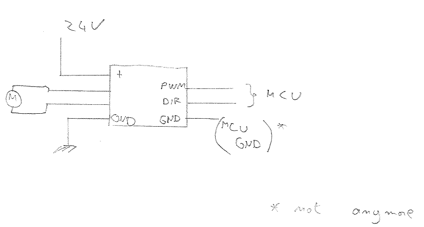
Moreover, I just remember that at one stage I connected the GND to the MCU GND (and after I realised that both grounds on the driver were already connected), but I cannot tell you if it was when the chip was working or not.
My MCU is on a arduino mega board and I really do not think the power supply is a problem here (power regulator is MC33269D, able to deliver 800mA). I do not have any problem with that board.
Here is how I connected the driver (is it what you was requesting ?):
It’s essential that your MCU ground be connected to your battery ground. Otherwise, the logic signals coming from the the MCU will be at a voltage not referenced to the the motor driver ground. If the logic inputs get much higher than 5V from GND, the inputs will break. Are you connecting the grounds in some other way?
Maybe there was an accidental short (maybe software, maybe wiring related) that broke IO pins on either the MCU or the motor driver or both.
Since the driver didn’t work with the MCU have you tried it in the lab setup again? Maybe it’s not broken? Are the IO pins on your MCU that were connected to the motor driver still functioning?
I can confirm you that my MCU is still working (including IO connected to the motor driver).
Moreover, as inputs of drivers are shorted to the ground, when I connect them to 5V it produces a short circuit.
Okay, yep, they sound broken and, from your description, I’m not sure how it happened. If you would like us to take a look at them, you can contact me at ryantm (at) pololu dot com for an RMA number and return shipping information.
I’ve got the same problem here. The pwm pin on the driver is shorted to the ground. I verified that the short is on the motor driver. I’ve the 18v15a version.
Did you guys find any solutions?
We have seen a few similar cases, but so far, we do not know what has caused the failures. The scenarios I remember tend to be similar to the one in this thread, where the motor driver is apparently working for a while but then stops working after it is moved to a different circuit or setup. That context generally makes it difficult to determine what happened since so many things are changing, and some inadvertent bad connections might be getting made when systems are being rebuilt.
What was your experience like? Did your driver work for a while, too, and if so, can you provide any information about what happened around the time of the failure?
In fact it’s pretty easy to explain. The driver was plugged in a bread board over the male header soldered. The circuit was working fine(with an Atmega 32). Than I’ve removed the header and soldered some wires to the pins(same configuration/circuit). Tested again but it didn’t work any more. I’ve checked the driver for shorts and contacts, all fine except a short between the PWM pin and the GND. I’m wondering if it’s the integrated circuit on the driver. What kind of chip is it? It has no label.