Hello,
I’m using the VNH5019 Motor Driver Carrier (Pololu - VNH5019 Motor Driver Carrier) to control a 12v motor with an ESP32. I have followed the wiring directions shown on the driver’s page. When all connections are done, the driver’s LED turns on. However, as soon as I connect the motor, the LED turns off. I am using a 12 volt DC power supply for the motor.
The test code i’m using is as follows:
#define MOTOR_IN1         21
#define MOTOR_IN2         12
#define PWMPIN            4
#define frequency         40000 //490
#define resolutionbit     8

int speed               = 255;

void setup() {
  Serial.begin(115200);
  Serial.println("VNH5019");
  Serial.println("**************************************");
  pinMode(MOTOR_IN1, OUTPUT);
  pinMode(MOTOR_IN2, OUTPUT);

  ledcAttachPin(PWMPIN, 0);  // assign the speed control PWM pin to a channel
  ledcSetup(0, frequency, resolutionbit);

}

void loop() {
  digitalWrite(MOTOR_IN1, HIGH);
  digitalWrite(MOTOR_IN2, LOW);
  ledcWrite(0,speed);
  delay(1);
}
Lastly, I noticed that when the motor is not connected, the voltage coming out of the motor pins is 5.16 volts which is about the same as what is being fed to the ESP32. shouldn’t that voltage be 12v or close to it?
Any help would be appreciated.
Thank you.
Hello.
Yes, at 100% duty cycle, the output voltage to the motor should be very close to your VIN voltage. Could you try measuring the voltage at the driver’s VIN pin while you are running your program? Could you post more information about your power supply and motor, like datasheets or links to where you got them?
Also, can you post some pictures of your setup that show all of your connections, including your solder joints?
- Patrick
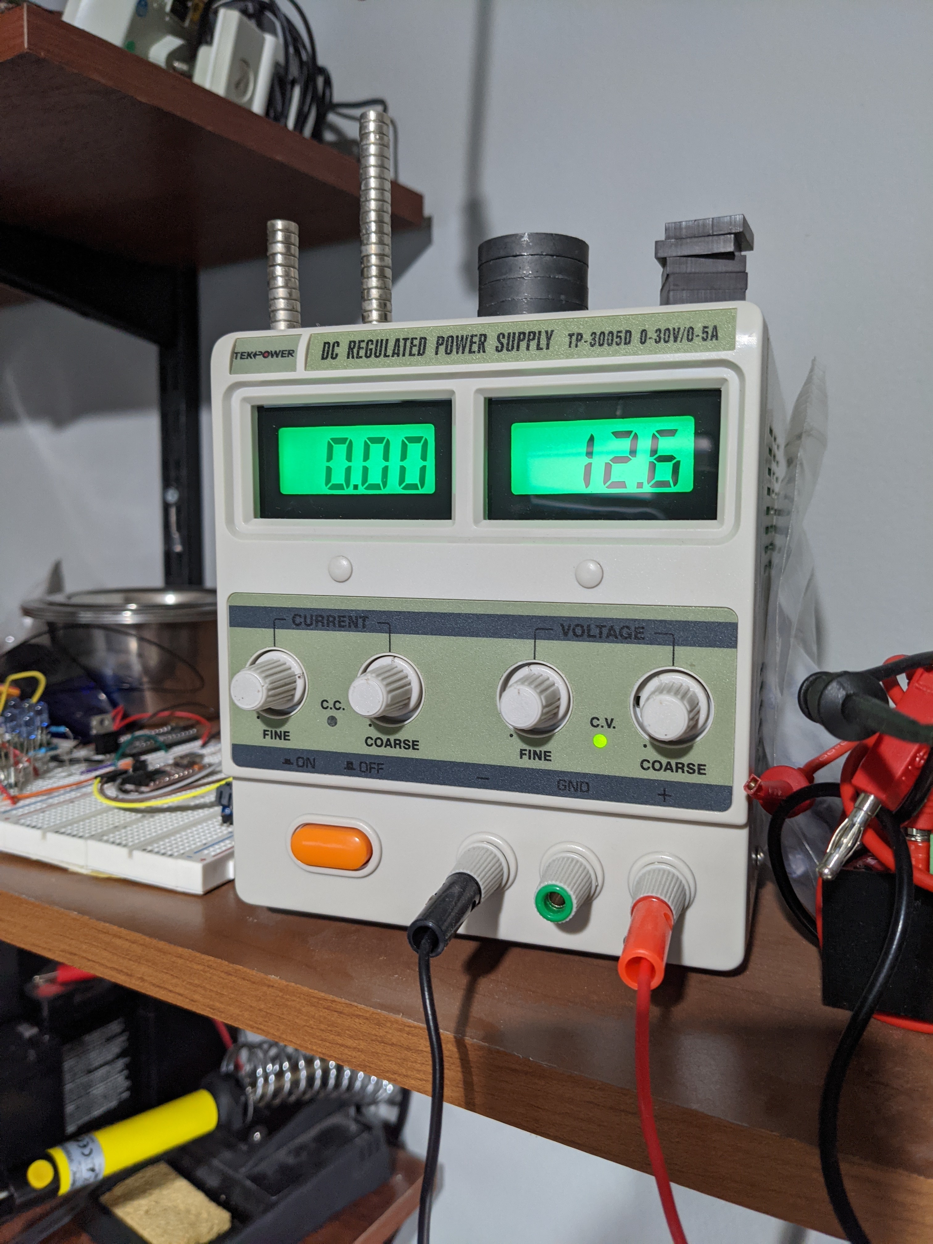
measuring the voltage at the driver’s VIN pin while you are running your program?
The voltage in the VIN pin is 12.6 volts. The voltage VDD is 5.5 volts
post more information about your power supply and motor
Power supply is a generic lab power supply (https://www.amazon.com/gp/product/B00LG1TGSE)
I’ve used two motors for testing. the one i want to use is this one (https://www.amazon.com/gp/product/B078J521TG/) and i have also tried a generic 12 to 18v motor (https://www.amazon.com/BestTong-RS-550s-18v-Electronic-Replacement/dp/B073WHPY7Z/)
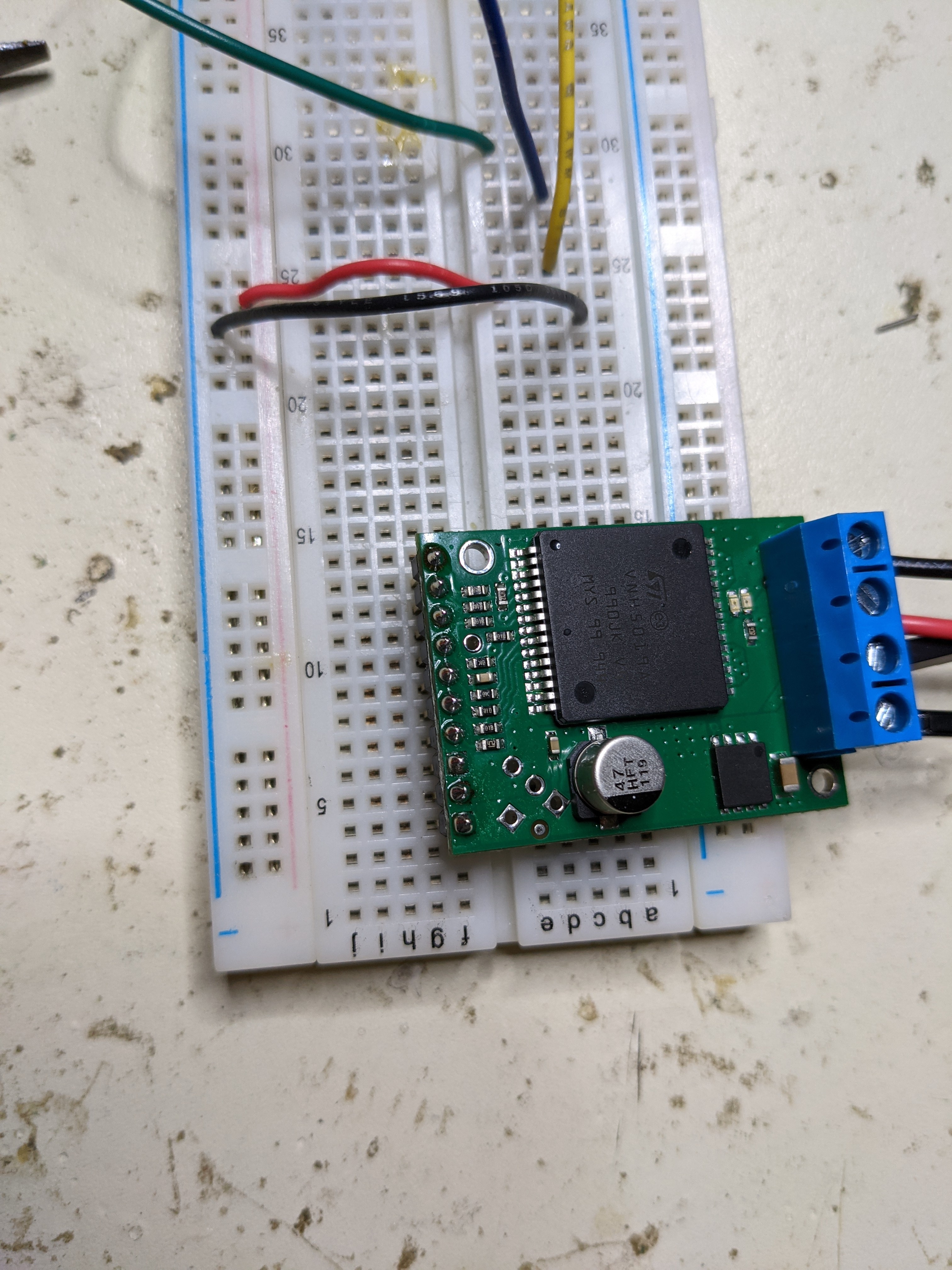
pictures of your setup that show all of your connections, including your solder joints?
The driver’s LED turns green as soon as it receives power from the microcontroller (in the VDD pin) and the power supply (in the VIN pin). However as soon as i connect the motor to the OUTA and OUTB, the LED turns off.
Thank you for your help with this!
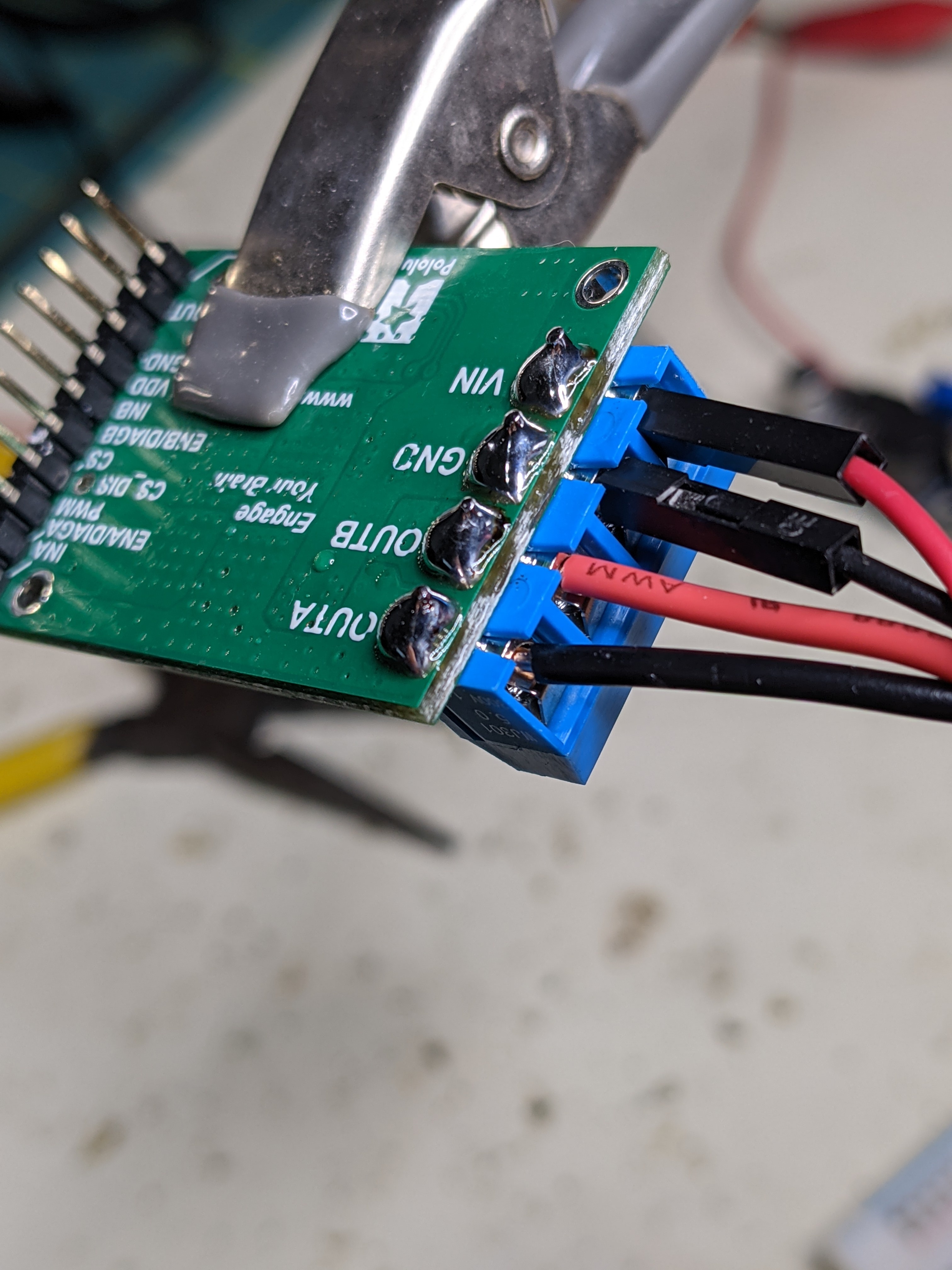
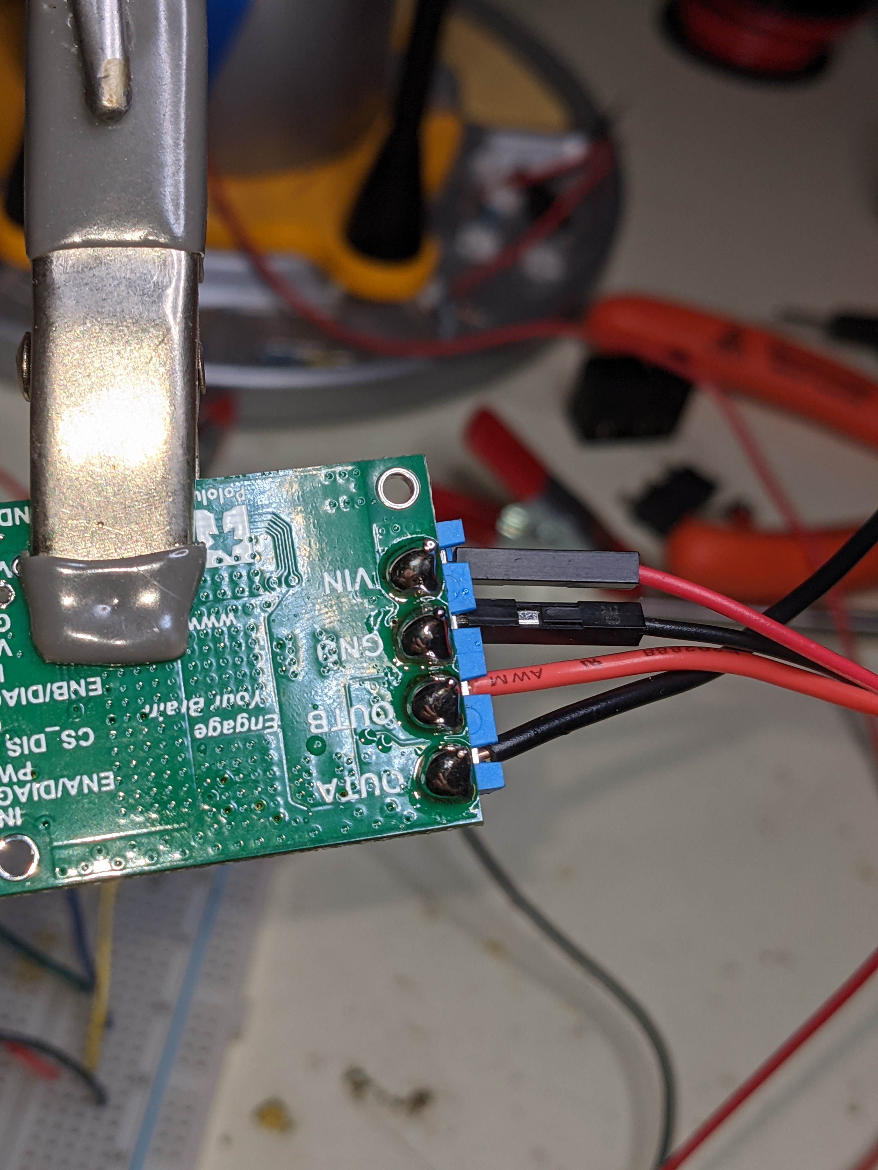
It looks like your terminal block solder joints to are not fully wetted to the pads, so they are probably not making good connections. It is harder to see your solder joints for the header, but some of those look like they could be suspect too. Can you try fixing those and testing your driver again, and if your driver continues not working can you post updated pictures? The Adafruit Guide to Excellent Soldering is a useful reference for that.
Also, I did not see any current specifications for the first motor you linked to, and it seems like the second motor might could potentially draw more current than the VNH5019 can handle. Can you try connecting both of your motors directly to your power supply (one at a time) to see if they work and how much current they draw? Ideally, if you happen to have access to one, it would also be good to look at their startup current using a scope with a current probe.
- Patrick
I retouched the soldering especially on the pins for the motor and the power supply. The problem continues.
I did not see any current specifications for the first motor you linked to, and it seems like the second motor might could potentially draw more current than the VNH5019 can handle.
I don’t have any more specifications from the first motor. The Amazon link is the only thing i have. As for the second motor, i thought the VNH5019 could handle 12 amp continuously. That motor hardly pulls more than 2 or 3 amps according to my power supply when connected directly to it.
thank you.
Does the first motor work if you connect it directly to the power supply?
The startup current for brushed DC motors like these can be many times higher than the free-run current. It can even briefly be as high as the stall current which for your second motor exceeds the 30A peak rating for the VNH5019. Do you have any smaller motors you could try? You might also try ramping the motor speed in your code to see if that helps get your motor started. You could do that by replacing the main loop from the program you posted above with this:
void loop() {
  // set direction
  digitalWrite(MOTOR_IN1, HIGH);
  digitalWrite(MOTOR_IN2, LOW);

  // ramp speed up
  for (int i = 0; i <= 255; i++){
    ledcWrite(0,i);
    delay(10);
  }

  // ramp speed down
  for (int i =255; i >=0; i--){
    ledcWrite(0,i);
    delay(10);
  }
}
- Patrick
Does the first motor work if you connect it directly to the power supply?
Yes. both motors run when connected directly to 12v from the popwer supply.
I don’t think the issue is with the code. Even when I upload a completely empty program, the issue is that as soon as i connect the motor to the driver, the LED turns off completely and no power goes to it. if the one of the motor connectors is disconnected the driver’s LED is on. if i change the code to change the direction of movement the LED changes color and stays on. As I complete the circuit connecting the motor to the driver, the LED turns off.
Just to clarify, I agree that the issue is probably not coming from your code, but one way to reduce the startup current (which I currently suspect is the cause of the problem) is to modify your code to ramp the voltage applied by the driver rather than applying it all at once. The indicator LEDs are connected to the motor driver outputs, so if they are turning off whenever you connect the motor then that suggests your motors are trying to draw more current than the driver will supply. Do your results change if you test a less powerful motor or ramp the driver outputs?
By the way, it sounds like you are connecting and disconnecting your motors to the driver while your programs are running. I suggest avoiding that in general, but especially to test if ramping has any affect you will definitely need the motor to be connected to the driver before your program starts.
- Patrick
Hi Patrick,
I tried your code and the result was the same. Here’s what I did:
- Loaded the new program in the ESP32 without the motor driver connected.
- unplugged the ESP32 and reconnected the driver without the motor
- powered up the ESP32. The driver’s LED turned green.
- powered off the ESP32
- connected power to the motor driver
- connected the motor to the driver
- turned power on for the ESP32. The LED on the motor driver did not turn on.
- disconnected the motor from the driver. motor driver LED turned ON immediately.
Thanks
Your procedure seems good. With the ramping code I posted the green LED should fade in and out with a period of about 5 seconds; is that happening when the motor is disconnected? What does the voltage across the motor outputs ramp up to if no motors are connected?
Could you also try testing the driver by itself? You can do that by connecting motor power, connecting your 5V supply to VDD/GND, connecting the PWM and INA pins to 5V, and connecting INB to GND.
- Patrick