Recently, I bought a motor driver and stepper motor only to realize the driver wasn’t rated for the required current of my motor. Before I buy a new driver, I would like to be extra sure my setup is sound! Links to my proposed setup are below:
Yes, the AMIS-30543 Stepper Motor Driver Carrier should work fine for driving that stepper motor.
Since stepper motors are essentially position-driven, you can precisely control the RPM of the stepper motor by controlling the frequency of the STEP signal. For example, the stepper motor has 200 full steps per revolution and uses a 51:1 gearbox, so if you want it to spin at 10 RPM in full step mode, you would need to step it at 102000 times per minute (200 × 51 × 10), which is 1700 pulses per second (pps). If you used half step mode instead, you would need to double that. You can refer to the stepper motor’s pull-out torque curve to get a general idea of the maximum speed it can achieve under the given conditions. It looks like the listing for your stepper motor links to the torque curve here.
Unlike most of our other stepper motor drivers, the AMIS-30543 needs to be enabled and configured through its SPI interface on each power up, and we do not have any Python examples for using it with a Raspberry Pi. You can find all of the resources we have available for it, including a link to our Arduino library, under the “Resources” tab of the product page.
Hi @BrandonM. Thanks for the help! Would you recommend any other drivers that would be compatible with this stepper motor and the Raspberry Pi I mentioned? Perhaps with more of a typical setup (e.g. not requiring SPI configuration upon setup, python examples available)? I want to be sure this will work before I buy another piece of hardware only to discover it won’t work with my setup.
You might consider one of our TB67S249FTG carriers, which come in a full breakout board version and a compact version, both of which can accept the more standard 2-pin STEP/DIR interface and are compatible directly with 3.3V systems like the Raspberry Pi.
Alternatively, you might consider the Tic T249 USB Multi-Interface Stepper Motor Controller, which is a more sophisticated controller that uses the same driver. While the Tics can be controlled from the same STEP/DIR interface, they offer several higher level interfaces such as USB, TTL serial, and I2C which feature additional options like speed limiting and acceleration limiting (i.e. speed ramping). This could be especially useful for a Raspberry Pi since the Raspberry Pi is typically not a good option for timing sensitive applications (like generating a steady step signal).
As for the TB67S249FTG, it looks like the compact version would not work as it only can support up to 1.6A. The full breakout board version looks like a possibility, however, I notice it’s rated for “approximately” 1.7A which is only 0.02A more than what my motor requires. Furthermore, the fact that this is only an approximation makes me a bit nervous. Is there any cause for concern here?
If this should be a concern, are there any other breakout boards in the same price range that would allow for a bigger buffer between the board’s rated current and the current my motor requires?
The Tic T249 is a bit more expensive than what I’m looking for, but if there are no more options I will consider it more.
It should generally be fine to run that stepper motor at a current limit of 1.6A, but doing so will result in slightly lower maximum torque and maximum speed, so whether or not that would be practical depends on your application. As for the full breakout version, our tests were done in ambient room temperatures in open air environments with no additional cooling. If you are running it in an enclosure, tight space, or warm environment, you might not be able to reach the same current before the over-temperature protections kick in. If you are particularly concerned about your setup, you could also consider using additional cooling (such as forced airflow) to increase your margin of safety.
Thanks a ton, the TB67S128FTG seems to provide a comfortable margin! Is there anything special about this driver I should be aware of? I’m quite new to all of this if you couldn’t already tell so I want to make sure I have all of my bases covered. I notice that the “minimum operating voltage” is 6.5 V. I should be ok then using a 12V power supply, no? Also, am I able to simply control this driver from the Raspberry Pi directly? I see a minimal wiring diagram in the product listing, but seeing how to connect to a raspberry pi specifically would be fantastic.
One other question - with my particular project, it’s possible that users will turn the motor by hand and end up putting volts back into the driver and/or Raspberry Pi. When turning the motor by hand, I’m not sure how many volts could actually be generated, but I’m wondering if there is any way to protect my components from getting fried.
Yes, a 12V supply should be fine. You might even consider using a higher voltage supply, as increasing the supply voltage can allow the stepper motor to reach higher step rates.
You can control the TB67S128FTG carrier from a Raspberry Pi. Unfortunately, we do not have any specific examples for doing so, but the minimal wiring diagram on the product page is still applicable for the required connections. Please note that since the Raspberry Pi boards operate at 3.3V, you should supply the IOREF, nSTANDBY, and ENABLE pins with 3.3V. The DIR and STEP pin connections can be made to whichever Raspberry Pi GPIO pins you want to use (and should match the ones used in your code).
Typically, the voltage generated from backdriving the motor makes its way back to the power supply, which could be a problem for some power supplies. Something like a shunt regulator or TVS diode could help in that case. Additionally, if the motor is backdriven fast enough that it generates voltage spikes in excess of the maximum operating voltage of your driver (44V), it could cause damage to that as well. If practical for your setup, you could also consider decoupling the motor from the system when it is being backdriven; however, please note that the making or breaking connections while the system is powered can also cause damage, so you should power the system down before doing doing this.
Can you please elaborate on what you mean by this? The Raspberry Pi only has two 3.3V power pins. Since I need 3.3V to be routed to three separate places (IOREF, STANDBY, AND ENABLE), how is this possible?
If you do not need to put the driver in standby or disable the outputs, you can tie all 3 pins to the same 3.3V source. There are many ways to make the physical connections. For example, you could make a custom 3-way jumper wire (that splits 1 connection to 3), you could solder jumper wires between the pins on the driver board, or you could use something like a breadboard to create a 3.3V bus that you can use to make multiple connections.
Alternatively, you can use separate GPIO pins to drive the nSTANDBY and ENABLE pins high, which allows you to have control over them later and put the driver in standby or disable the outputs.
So I’m able to use GPIO pins to control the nSTANDBY (is this different than STANDBY without the ‘n’ prefix) and ENABLE pins. What about the IOREF pin?
Alternatively, you can use separate GPIO pins to drive the nSTANDBY and ENABLE pins high, which allows you to have control over them later and put the driver in standby or disable the outputs.
In my previous setup that used a HAT to control the stepper, I was able to “release” the motor, which prevented it from getting hot. Are you referring to something similar here? What is the difference between putting it in standby vs disabling the outputs?
I would not recommend using a GPIO pin to supply IOREF. If it gets driven low (either on accident or even during boot up, which can happen sporadically while everything is in an undefined state), it could cause issues and possibly damage.
To clarify, I have been using the “n” before STANDBY to designate it as an input that has inverse functionality (this is done on the board and product page with a bar over the word, but the forum does not easily support that syntax). So, it essentially specifies that the standby mode is enabled when the input is driven low.
To disable the stepper motor like you described, you can drive either the ENABLE or nSTANDBY pin low. You can reference the TB67S128FTG driver’s datasheet, which can be found under the “Resources” tab of the product page, for the difference between the two. In short, the ENABLE function turns off the MOSFETs and the output lines become high impedance, and the nSTANDBY function stops the internal oscillating circuit and a motor outputs.
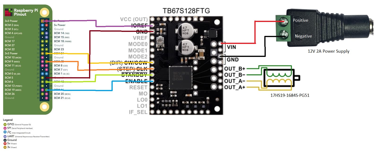
Thanks! So here is how I would be wiring up my stepper/RPi, and power supply to the pins on the driver. Does this all check out? And Alternatively, I could wire IOREF, STANDBY, and ENABLE from the same 3.3V Power pin? And this should allow me to achieve the maximum torque possible from my stepper?
Lastly, I know some people put a capacitor between the power supply and the driver. Is this necessary? If so, how can I achieve this? Do I solder the capacitor onto the driver, or do I solder it to the wires between the driver and the power supply?
Thanks a ton for all your help and please forgive my ignorance.
You can connect IOREF, nSTANDBY, and ENABLE all to the 3v3 power pin on the Raspberry Pi, but you would not be able to de-energize the motor while the rest of the system is powered like you described before.
Please note that the IOREF, nSTANDBY, and ENABLE connections are not going to affect the maximum achievable torque from your stepper motor. There are a variety of factors that can impact the maximum torque, most of which are specific to your setup. The 3 most prominent factors are probably the current limit, the operating voltage, and the microstepping mode. You should follow the instructions under the “Setting the current limit” heading on the driver’s product page to set the current limit to an appropriate value for your stepper motor. If you need additional power, I suggest trying to increase your operating voltage (for example, using 24V or 36V). Since the driver is current limiting, this will not increase the holding torque of the motor, but it will increase the load it can handle since the current will be able to ramp up faster at each step. Lastly, microstepping significantly reduces how much torque a stepper motor can apply per microstep. Here is an application note with more details about that.
The driver already has some capacitors on the motor supply voltage line, which is probably enough for most applications. If you do need to add more, I recommend adding them between the VIN and GND lines as close to the board as possible.
You can connect IOREF, nSTANDBY, and ENABLE all to the 3v3 power pin on the Raspberry Pi, but you would not be able to de-energize the motor while the rest of the system is powered like you described before.
Yep, that’s why I made the diagram as I did! This way, I can cut off power to the motor when it’s not in use to keep it from getting too hot.
Thanks for everything. I think I should be good to buy this driver now!
Sorry, one last question. There will either be approximately 6 feet of wire, either between the controller and the driver or the driver and the motor. Will this pose any issues? If so, how can I overcome them?
It is typically better to keep the driver closer to the controller and have the longer length of wire between the driver and the motor. Long wires will add some resistance to the load, which you could probably account for if necessary. I recommend measuring the wire resistance to get a better idea of what you’re working with.