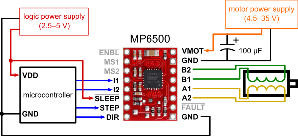
I’m using an Arduino Mega to control a NEMA 17 motor: Stepper Motor (2.8V, 1.7A/Phase) I’m using the MP6500 driver. I bought the version with digital current control and the pin headers already soldered.
I’m unable to get the simple test program that is used to test stepper motors to make the motor do anything. (This program was posted on the Arduino forum many years ago and it’s supposedly one of the simplest ways to test a stepper driver that uses STEP/DIR and a stepper motor.) I hear no humming, no vibration and no movement. Here’s the code:
byte directionPin = 23;
byte stepPin = 25;
int numberOfSteps = 100;
byte ledPin = 13;
int pulseWidthMicros = 20; // microseconds
int millisbetweenSteps = 250; // milliseconds - or try 1000 for slower steps
void setup() {
Serial.begin(9600);
Serial.println(“Starting StepperTest”);
digitalWrite(ledPin, LOW);
delay(2000);
pinMode(directionPin, OUTPUT);
pinMode(stepPin, OUTPUT);
pinMode(ledPin, OUTPUT);
digitalWrite(directionPin, HIGH);
for(int n = 0; n < numberOfSteps; n++) {
digitalWrite(stepPin, HIGH);
delayMicroseconds(pulseWidthMicros); // this line is probably unnecessary
digitalWrite(stepPin, LOW);
delay(millisbetweenSteps);
digitalWrite(ledPin, !digitalRead(ledPin));
}
delay(3000);
digitalWrite(directionPin, LOW);
for(int n = 0; n < numberOfSteps; n++) {
digitalWrite(stepPin, HIGH);
// delayMicroseconds(pulseWidthMicros); // probably not needed
digitalWrite(stepPin, LOW);
delay(millisbetweenSteps);
digitalWrite(ledPin, !digitalRead(ledPin));
}
}
void loop() { }
Basically, the code just makes the motor take 100 steps one direction and then 100 steps in the other direction.
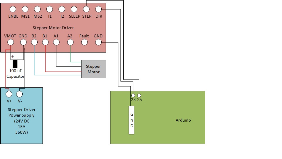
A schematic of the circuit is attached. I’ve stripped it down to the bare minimum.
Here’s what I’ve tested/measured.
Before hooking up the motor to the driver, I used a multimeter to test continuity between the 4 wires. The first 2 wires that I got continuity on, I labeled A1 and A2 and the other 2 were labeled B1 and B2. I read somewhere that these leads have no polarity so it should not matter which wire gets plugged into A1 on the driver, just as long as the other wire that shares continuity gets plugged into A2. If that’s wrong, please say so.
I’ve verified that I have 24V coming to VMOT/GND. I took a measurement at the MP6500 itself. While the program is running, I see the LED on the Arduino flashing, which indicates it is running thru the code to send the pulses to the STEP pin. Also, while the LED is flashing, I put a multimeter across the A1 and A2 terminals and also across the B1 and B2 terminals. I measure absolutely no voltage.
This is the first thing I’ve tried to do with this driver and motor. Can someone please tell me if it’s pretty likely that the driver board is dead.