
Hi, I have been using, very successfully for the past year, the JRK 12v12 motor controller in the PWM input mode with the PWM signal coming from the Orangutan SVP 1284 RC Servo outputs. I have not made any changes to my setup that I am aware of but I no longer receiving a valid input (the JRK red led is on and the errors tab on the JRK configuration utility confirms it is the Input Invalid error. I have several JRK’s and several Orangutan SVP’s so I tried several combinations to see if I had a bad board but all combinations worked exactly the same. I am providing PWM inputs to 3 JRK’s from the servo demux, (pins 0,1 &2). I have verfied that the demux pins on the SVP seem to be working fine by plugging in a Hitec HS81 pwm servo into each of the 3 outputs. The servo responds perfectly from each of the 3 demux pins. The JRK’s work fine in the serial mode. I loaded several of the example “servo” programs onto the SVP. Again the Hitec RC servo responded as per the description in the program but none of the JRK’s (I have 6) will accept this as a valid input. I reset both the JRK’s and SVP’s but that did not help. I restored the JRK’s defaults but no change. It is not likely that 6 JRK’s or SVP’s suddenly failed all in an identical manner so I am guessing it is an issue that I have created. I am using a 0-5v pot for feedback for the JRK which still works fine in serial mode. other than the feedback connection the only other pin I am using on the JRK is the RX line that connects back to the servo signal pin on the SVP. I have a 12v power supply running parallel with a 12 v hobby battery and all of this works very well in serial mode. This set up has been working flawlessly to this point, I have completed this setup many times and have never had this error before. Any suggestions?
Hi,
I am sorry you are having problems with your jrk motor controller and Orangutan robot controller. Are you testing each of your jrks and Orangutan SVPs in separate setups or is there some component in common between all the setups (e.g. a wire)? I suspect there might be a bad connection between the jrk and the Orangutan SVP. Could you turn off the power to your jrk and SVP, and check for continuity between the jrk’s RX line and the SVP’s servo output using a multimeter?
Even though your jrks worked in serial mode, that does not necessarily mean you are controlling it through the RX pin, so the RX pin might be damaged. Do you have an oscilloscope available to measure the RC servo pulses on the jrk’s RX line?
- Zeeshan
Thanks Zeeshan. I do not have a scope, so my next best test was to use the hobby servo, I figured if it worked then the signal was likely valid coming from the SVP servo demux. I tried multiple jumpers to ensure that a common problem was not the cause. I am quite certain that it is not an RX pin as I have several JRK’s for which I am getting the same result (this would tend to lead you to the “common issue” problem like the lead from the servo pin to the rx pin). I am using jumpers which I bought from Pololu and I have a bag of them so I tried several jumpers and used the jumpers for other inputs just to confirm that they were working
I am not quite sure I follow you on checking between the RX pin and the servo demux pin for continuity. I can and have checked the jumper wire to ensure it is fine but without the jumper in place what would I check with the multi meter?
When I am in serial mode I am only positioning the JRK from the configuration utility so you are correct that that does not confirm the RX pin is working but only that the rest of the JRK seems to be working fine, If I was only having the issue on one JRK receiving an input from one SVP I could buy the idea of a bad pin, but I have at least 6 JRK’s and 4 SVP’s, some are unused, and I cannot get any of them to receive the PWM input.
Could you post a wiring diagram and some pictures of your setup?
- Zeeshan
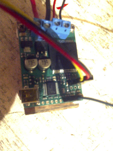
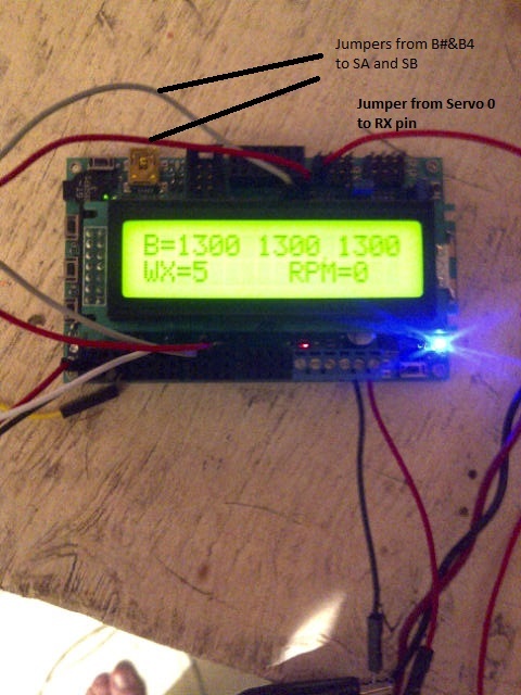
Hi Zeeshan, I have attached a couple of pictures of my set up on the test bench. The display is representing the get servo target value for 0,1,&2. I have jumpers from b3 and b4 to SA and SB. One jumper from servo 0 signal pin to the RX pin on the JRK. I have a 0 to 5 volt pot fed into the FB pin on the JRK. I realize in the picture that the jumper going from servo pin 0 is red in the picture of the SVP and black on the one of the JRK, just a timing issue of when I was trouble shooting and trying different jumpers. The wires coming into the analog port of the SVP are another 0-5 volt pot that I use to determine the calculated values for the servo positions.
lcd_goto_xy(0, 0);
print(“B=”);
print_long(get_servo_target(0)); // print the PWM target position (Blade #1)
print(" “); // overwrite any left over digits
print_long(get_servo_target(1)); // print the PWM target position (Blade #2)
print(” “); // overwrite any left over digits
print_long(get_servo_target(2)); // print the PWM target position (Blade #3)
print(” "); // overwrite any left over digits
Do you have a GND connection between the SVP and jrk? I am unable to see one from the photos you posted. Also, did you solder on the terminal blocks and pins to your jrk?
Additionally, could you post your jrk settings file so I can check your settings?
- Zeeshan
Thanks Zeeshan. I ran a ground from the svp to the jrk and problem is solved. Just so I understand on my actual setup I am using one power supply, so the ground to the svp and the jrk is common, on my test bench I was using two different power supplies, one for each device. On my actual set up is the power supply ground acting as the common ground? Should I as a practice run a separate ground between the devices even if they have a common power supply? Thanks for you help, much appreciated
Golf
I am glad your problem has been solved. Even if you have a common ground through your power supply, it is good practice to still directly connect the grounds of your two devices to ensure they really are at the same level.
- Zeeshan
The problem with that “extra” ground connection is that you’ll be creating a so-called ground-loop.
The problem with a ground loop is that if there is a (changing) magnetic field through the loop, the loop will act as a transformer. As there is only one winding, the voltage might be low, but the current can be quite high, causing the thinner parts of your loop to fry, or an audible hum in audio circuits.
There is no “quick and easy” answer. Zeeshan’s answer ensures that you get a working setup even if you decide to go back to the separate powersupplies setup.
The best way would be to run the powersupply ground wire to somewhere between the two devices, and then fork both ways. This ensures a ground connection between the two and very little (if any) ground loop.