Industrial Application of G2 - VM voltage Issues to Controllers

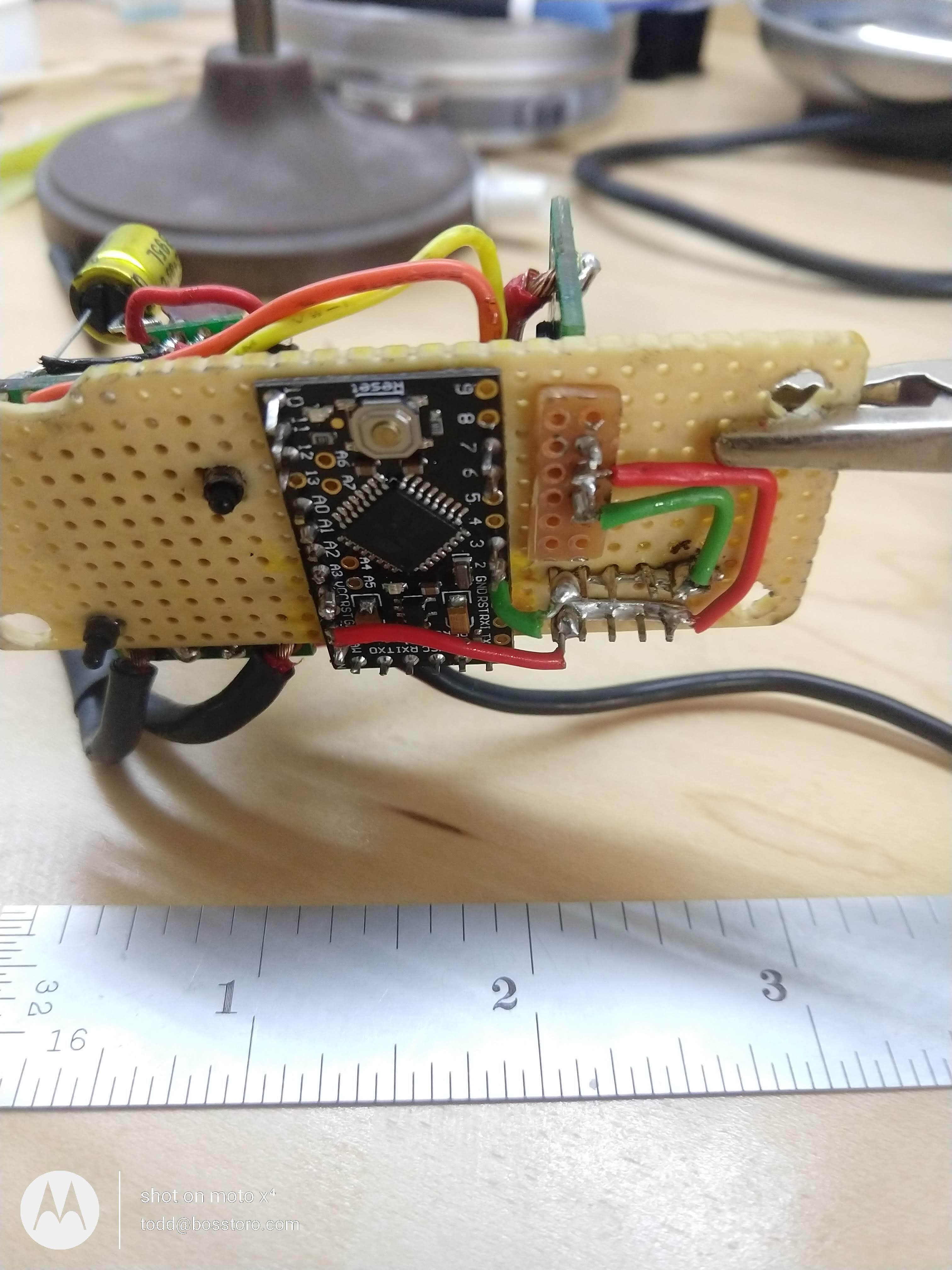
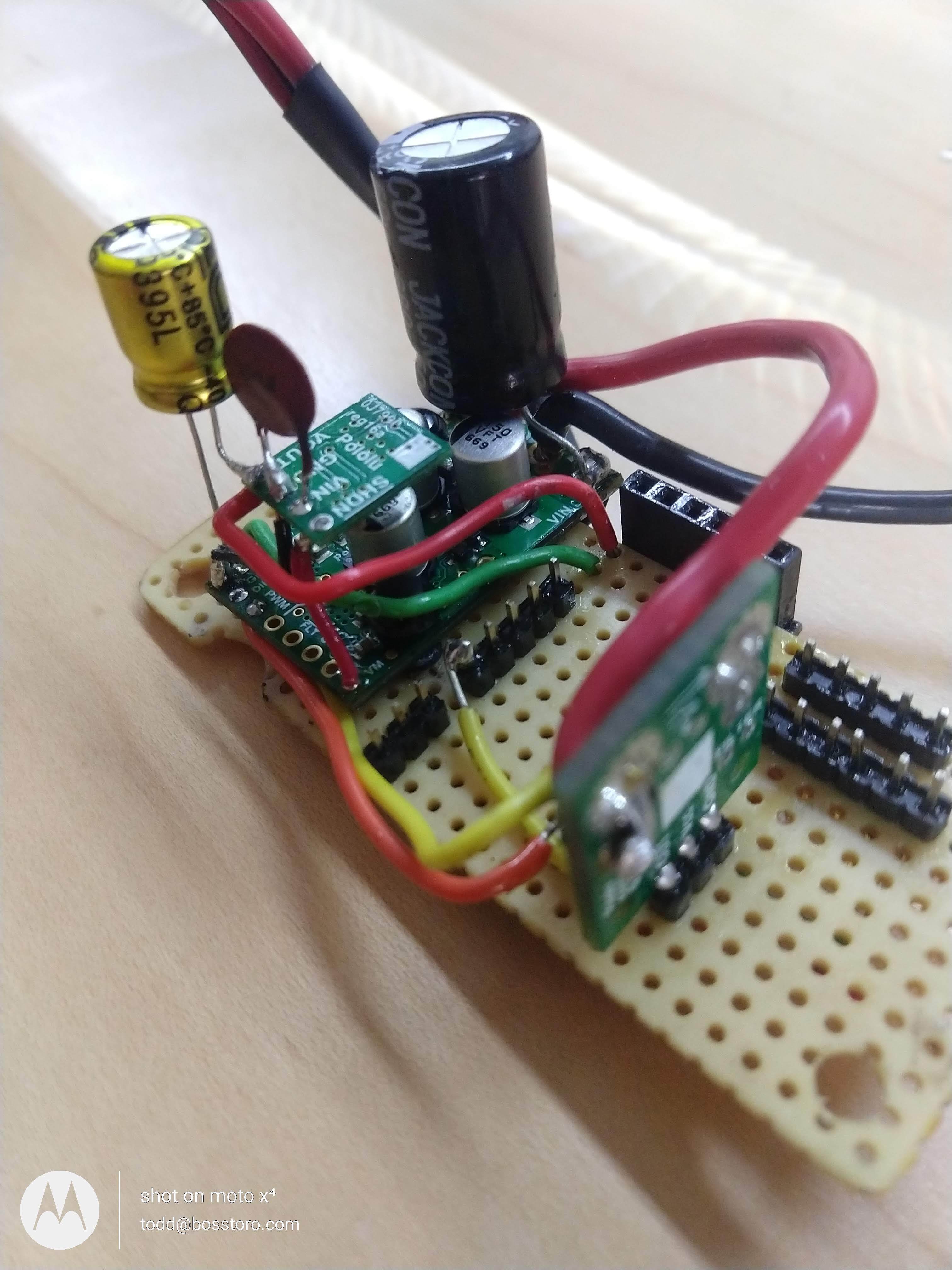
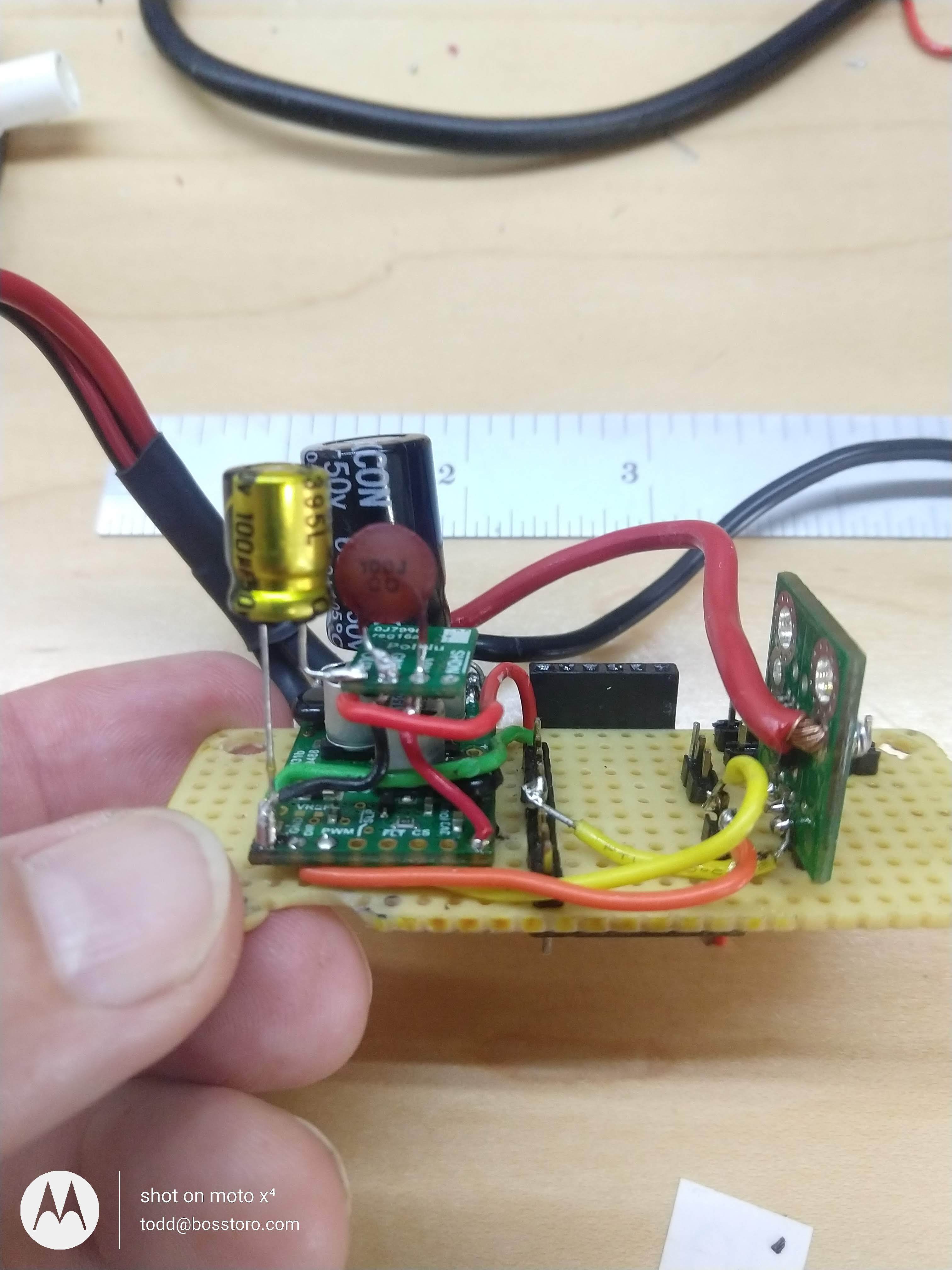
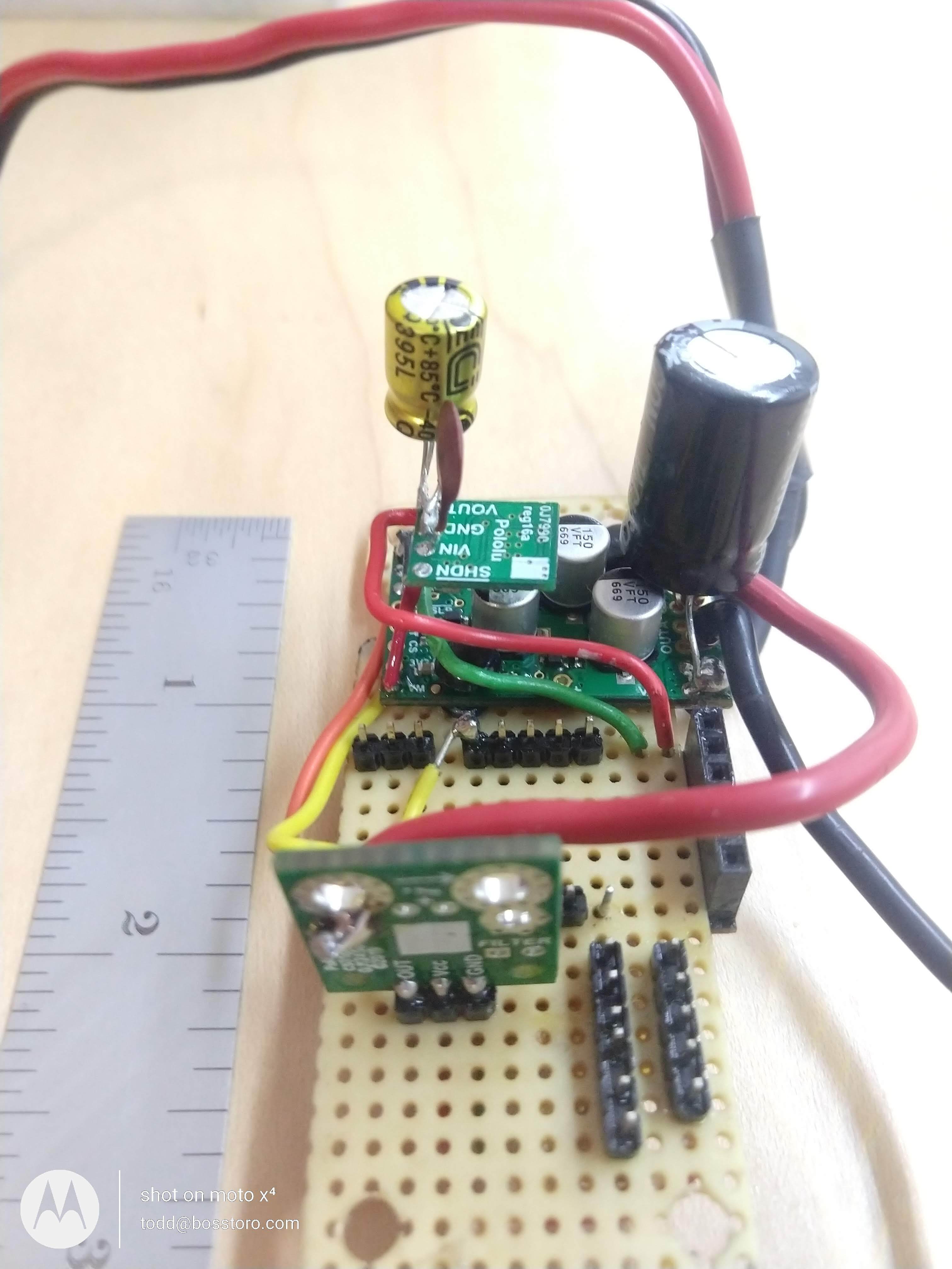
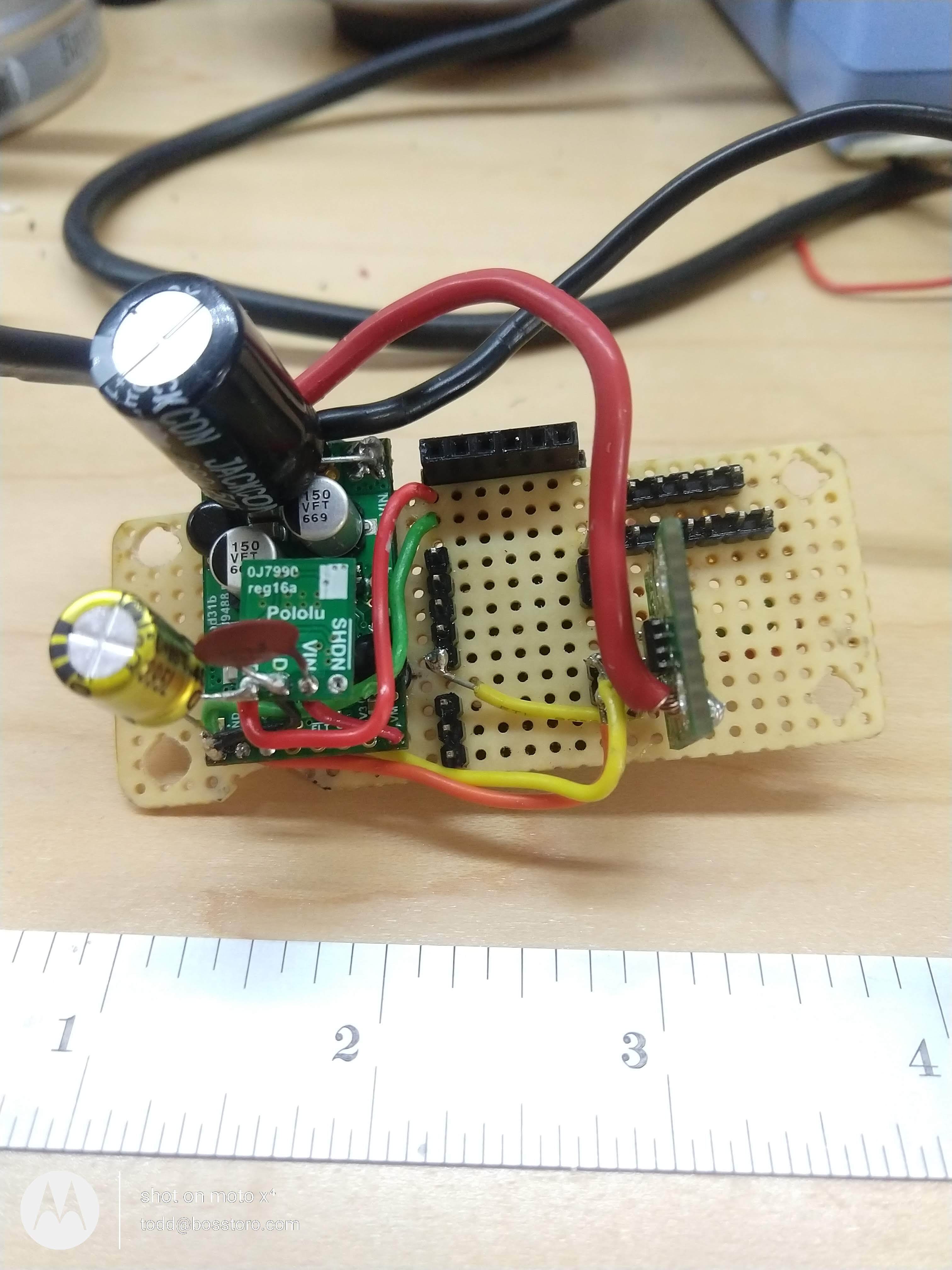
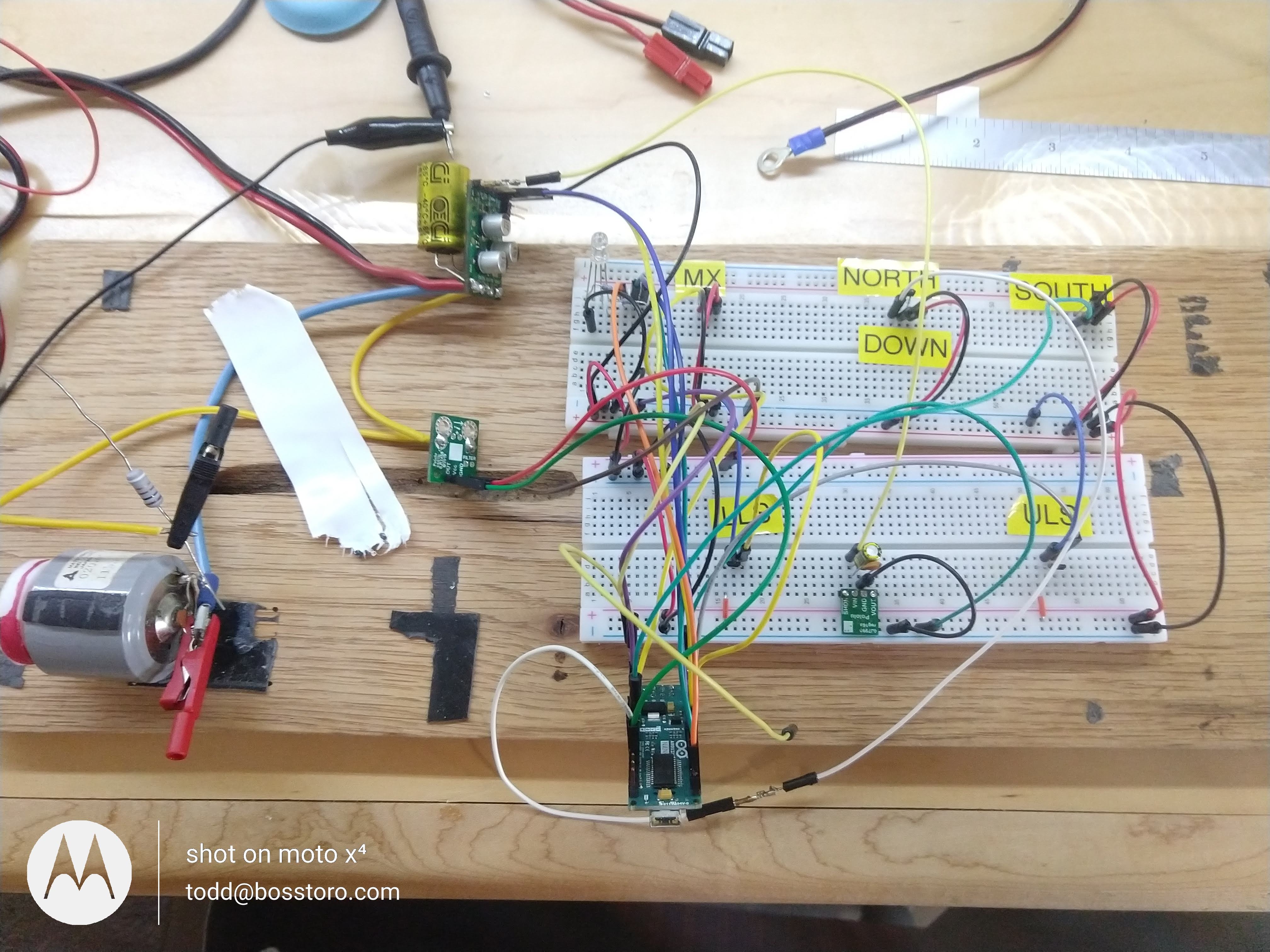
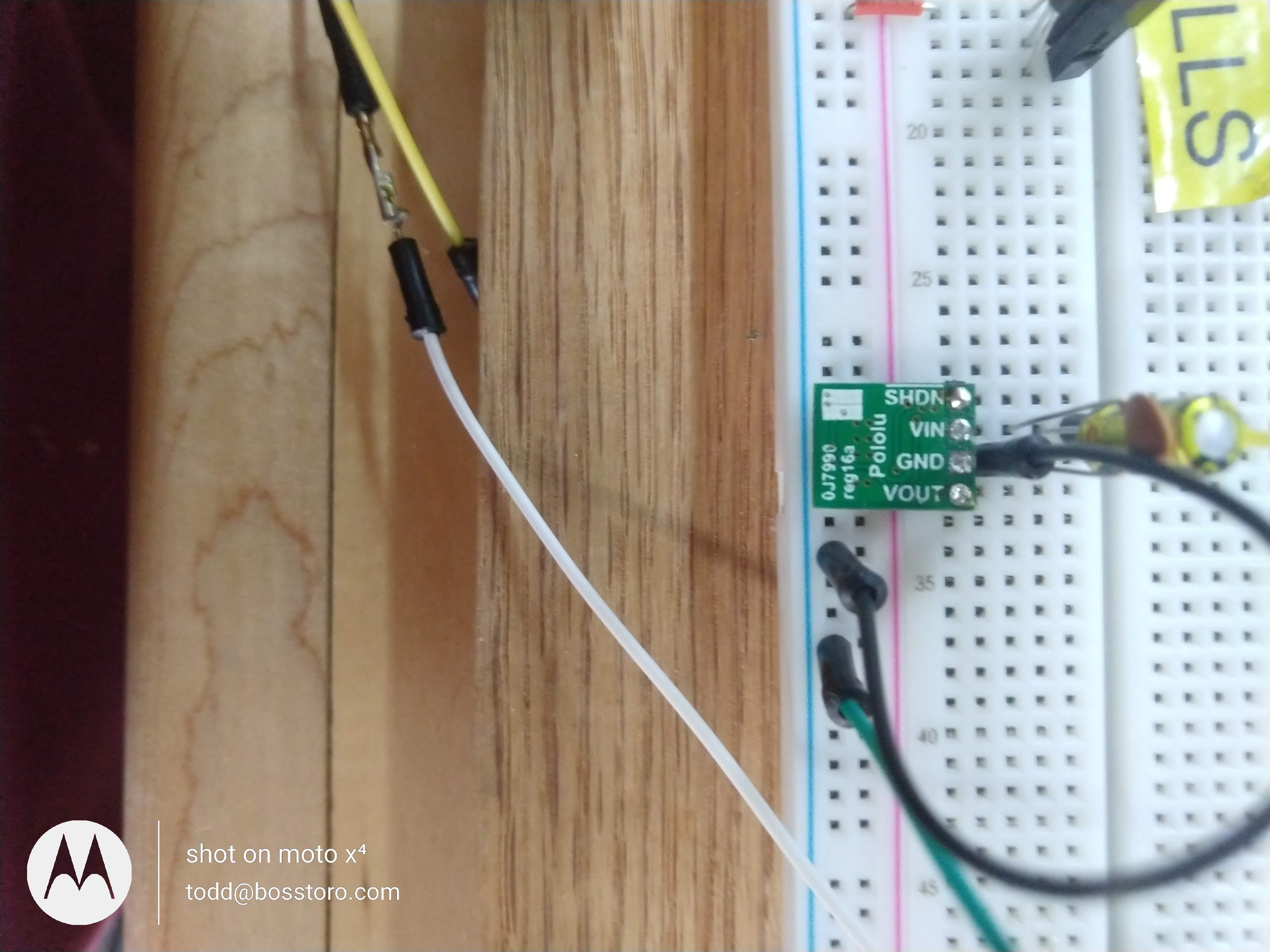
Our prototype Electric Cylinder control system is using Pololus G2 18V25 Motor Driver and a D24V5F9 to power the microchip controller.

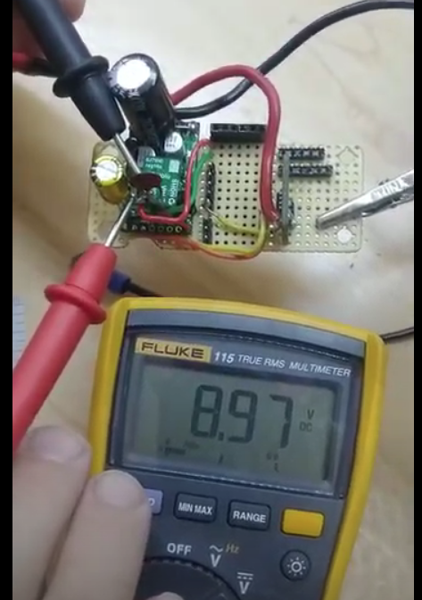
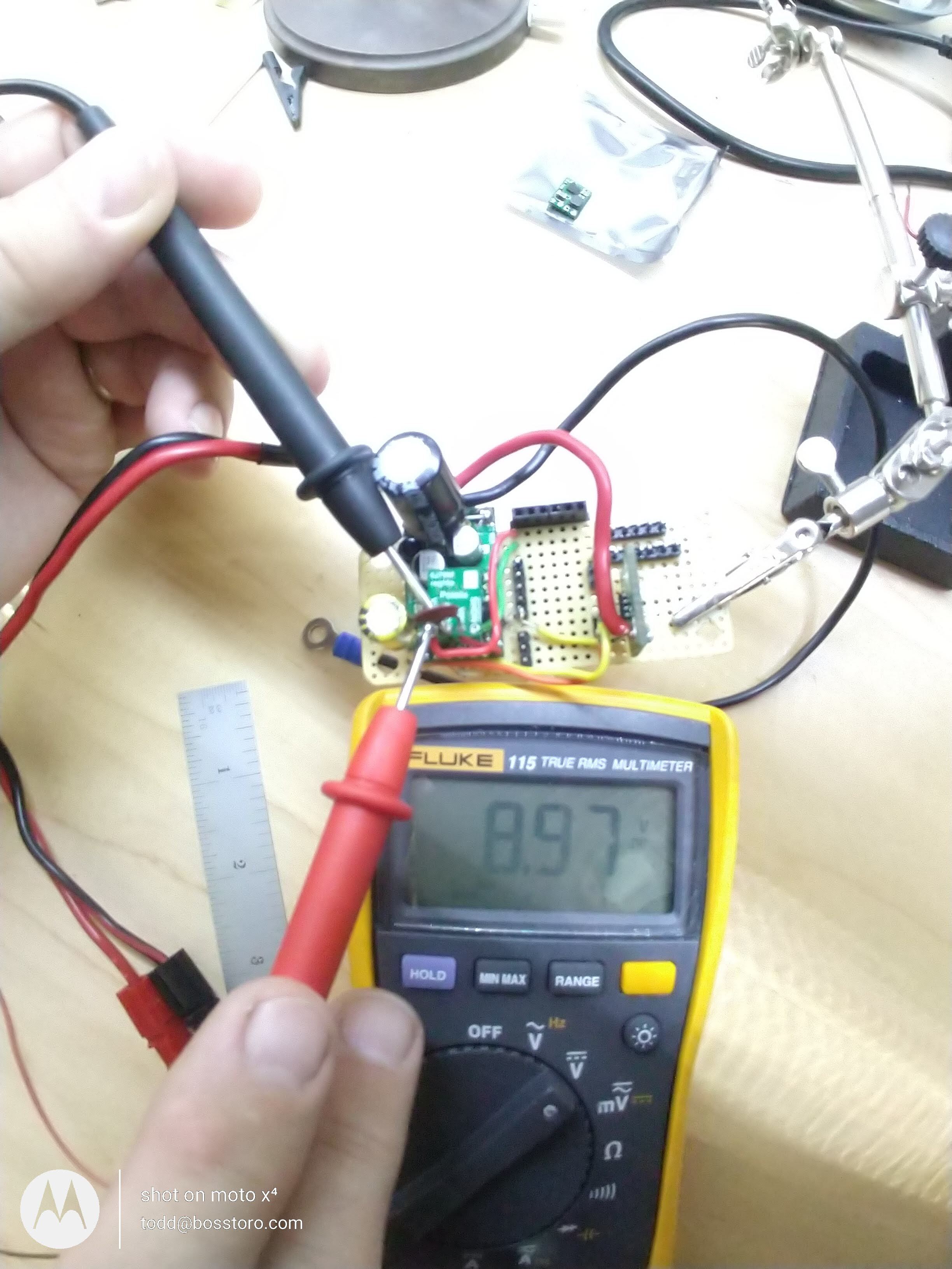
Bench results on the motor driver are good! We started in August 2020 using a 12VDC 10 Amp benchtop power supply in initial tests and the G2 was performing great! The D24V5F09 powered from the VM and GRD of the G2 is working, we measure 9.48VDC on Vout and GRD.

Our full load testing of our Electric Cylinder started Aug 12th. The test controllers, MicroChip, DFRobot Beetle controllers were not happy. MicroChip fails to power up and DF seems to forget the program after <10mins of operating?

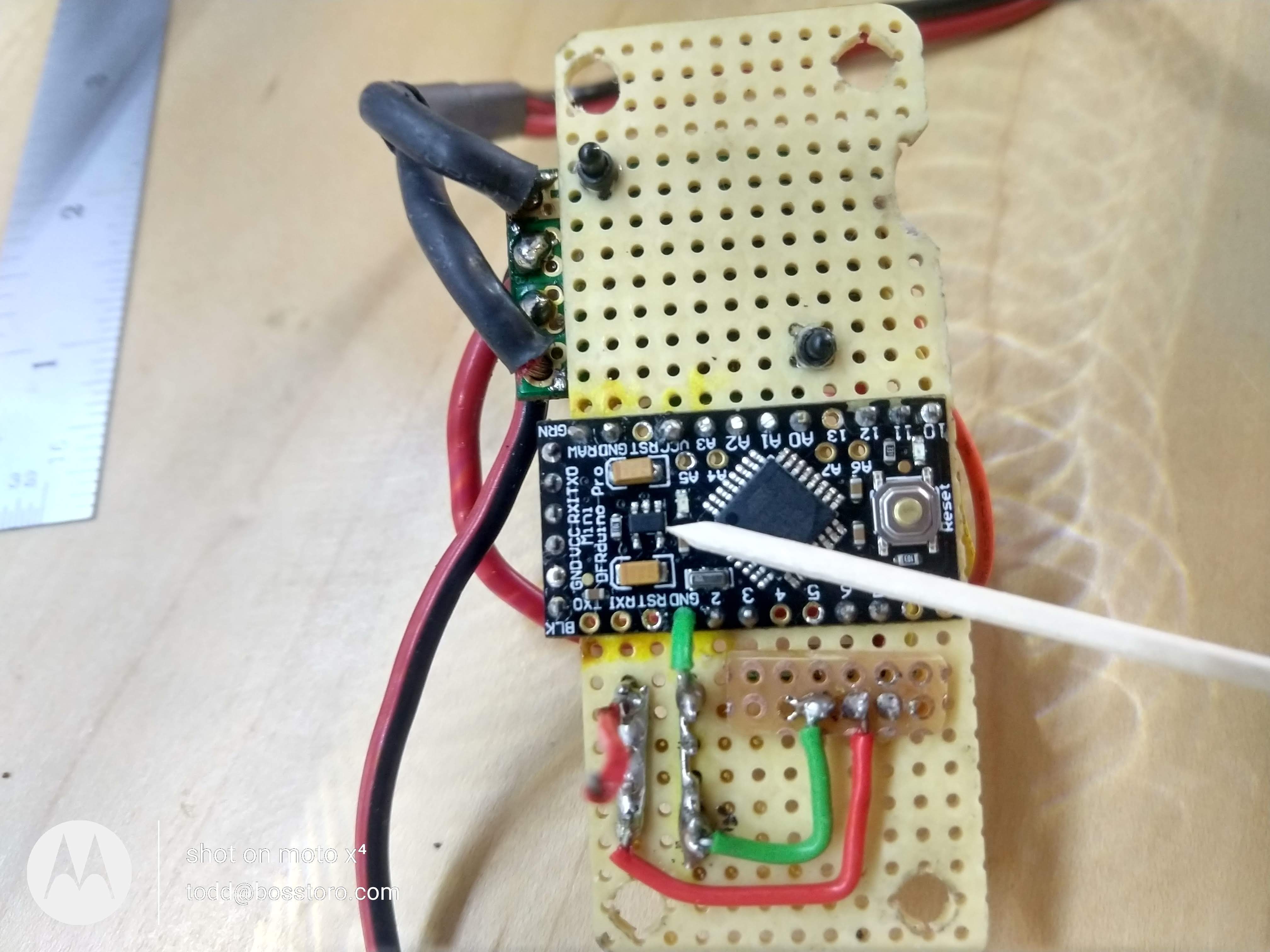
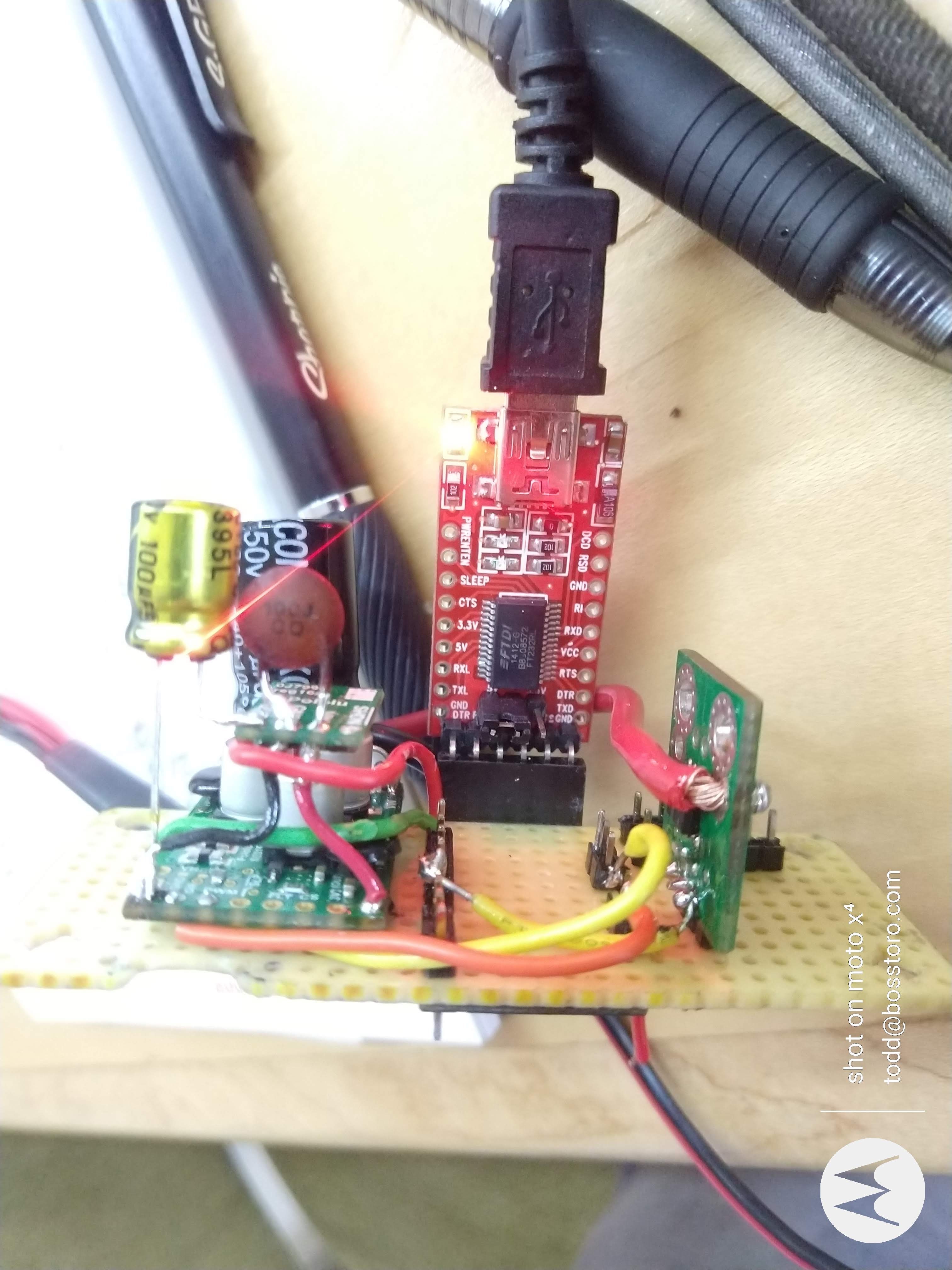
On Aug 24 we installed a Arduino Pro Mini with a 100uF capacitor, and a ceramic 10pF on V out and Grd of the D24V5F9. No luck with the arduio pro mini controller. We trouble shot the soldering, the capacitors, the voltage,NO Luck!

We measure 9.48VDC on the Pro Mini Raw and GRD pins,but the DFRobot Pro Mini copy is NOT powering up? The VCC out and GRD voltage is .248VDC - so,we asked Jameco tech for help. They suggested checking the onboard voltage regulator,9.48V on pins Vin, Grd. The Vout and Vgrd only measure .249VDC? Jameco is mystified.

Replaced on board power regulator with a Ti 1117,same .247 Voltage out,so,we probably damaged it somehow? Nothing against DFRobot, Notthing against Jameco, we move ahead with orginal, COO Italy made Arduino Nano!

Sept 11, received 2 "Spanking Brand New COO Italy made Arduino Nano’s from Jameco,arrived and were installing them on the test breadboard.

Pics are our integration build using the Pro Mini. that we could NOT get to power up without a FTDI controller?

Thanks Pololu - Boss Toro C/O Todd C

Some Pics of the D24V5F9 Voltage from a G2 18V25 Motor Driver of our industrial prototype.

Thanks Pololu - Boss Toro - Todd C

Hi.

I moved your post to the Support > Other Pololu products sub-forum since it seems you would like help troubleshooting and are not just sharing your project.

I am sorry to hear you are having trouble with your G2 High-Power Motor Driver 18v25 and D24V5F9 regulator. It is hard for me to follow how everything is connected in your system. Could you post a wiring diagram for the whole setup? It sounds like your issue is that none of the microcontroller boards you tried worked; is that correct?

You mentioned measuring about 9.5V out of the regulator, but your last picture shows a reading close to 9V. If the regulator was outputting 9.5V, that might indicate something wrong. Was it outputting 9.5V or was that a typing mistake?

-Claire

Hi Claire! YES, we are not sure what is going on?
Thank You on reaching out,yes, I would prefer sending our IP circuit via email, vs. uploading to the forum.

Individually,the Pololu products work (Very Well).

We are having to power the microcontroller from a second benchtop AC to DC converter connecting via typical mini or micro USB connectors?

Today, (Tuesday, 15 Sept) using the breadboards,i installed the Jameco supplied OEM Arduino Nano,wont power up from the D24?

It will power up if i use jumpers from the G2’s VM and GRD pins to Vin and GRD,BUT the Nano’s on board power reg gets suddenly gets hot to the touch ,1 min and its hot?

On and Off the project board the D24’s (we have two), both work as advertised, 11.50-18Vcc in,gets a smooth 8.99Vcc /494-522mA on our test bench (Mega-Watt power supply and Rigol Scope)??

We are not sure what is wrong?

So, we think the issue is either 1) our 4th grade circuit design or 2) our 1st grade soldering/fab technique?

See attached schematic and MS Power Point,we have alot of teammates who prefer pictures vs. schmatics,when we do in house team meetings?

Any suggestion is warmly welcomed Clair - Thanks Todd

Thank You on this.

Todd Canterbury

Boss Toro Electromotive SA 562-552-0347 *[todd@bosstoro.com](mailto:todd@bosstoro.com)*

The Boss Toro Electromotive SA team designs, develops and manufactures electric cylinder technologies for precision movement or high torque applications in the industrial, powers sports, medical, aerospace and marine industries. We are committed to reducing the environmental impact of traditional hydromotive systems with an environmentally responsible, sustainable and efficient electromotive technology.

Boss Toro 15 Sept for Pololu.pptx (1.1 MB)

Hi, Todd.

I just wanted to point out that it looks like you used the “reply via email” feature of the forum, so your latest message is currently publicly visible in the forum topic that you started. Given what you wrote, I’m not sure if that is what you intended to do, so if you included any sensitive information by mistake, you might want to edit or delete your forum post. (In case you are reading the email notification for this post as well, you should be able to find the link to the forum topic at the bottom of the email.)

Kevin

Some of your soldering, especially on the motor driver power pins does not look great, and it is possible that is the issue. Let’s simplify things. Can you disconnect everything from your Arduino Nano and try powering it through the regulator with the regulator powered directly from your 11.5V source? If that works, you can try adding your peripherals back one at a time until you start to have issues.

By the way, the regulator on the Arduino Nano is a linear regulator, so when stepping-down it dissipates the excess energy as heat. The larger the input to output voltage difference, the more heat. So, it is not unusual for the regulator on the Nano to get hot with an input of 12V, especially if there is extra load on the 5V line.

-Claire

Some of your soldering, especially on the motor driver power pins does not look great, and it is possible that is the issue. Let’s simplify things.

Can you be more specific on the location of the “motor driver pins” might i get you to refer to a specific foto we shared with you Clair?

Can you disconnect everything from your Arduino Nano and try powering it through the regulator with the regulator powered directly from your 11.5V source?

We did that before contacting Pololu - see foto of bread board. Even set D24 up as you suggest,smooth 9.00Vcc, very little ripple on the Rigol scope,NLT 480mA output also. Both units,so, were perplexed Clair?

If that works, you can try adding your peripherals back one at a time until you start to have issues.

Again Clair,that is the point we are at now,and the D24 is not working? Can you possiblly review our voltage circuit design from the MSPPT we sent over. Specificlly the design between the G2’s VM and GRD pins to the Nano Vin and Grd pins. Additionally, our Fluke displays 8.99vcc on the Vin and Vout pins of the D24 with it connected to the G2’s VM and GRD pins and the G2 being powered as you suggest above,from the Mega Watt @ 11.5Vcc to the at the G2’s Vin and Grd pins? Soo,wee stumped?

By the way, the regulator on the Arduino Nano is a linear regulator, so when stepping-down it dissipates the excess energy as heat.

Yes, we understand and are aware of this.

The larger the input to output voltage difference, the more heat. So, it is not unusual for the regulator on the Nano to get hot with an input of 12V, especially if there is extra load on the 5V line.

Can you possibley evaluate ands ID any issue with the selected components and their locations in the circuit design between the G2’s VM and GRD pins and the Raw (or Vin) and GRD pins of the Nano? See the previously attached MSPPT build schmatic? We would very much appreciate any expert opinion here Clair?

Thank You Clair,we sincerly appr the help.

By motor power pins I mean the large VIN and GND pins beside OUTA and OUTB. They are likely connected well enough, but especially for higher power pins, you should be able to see solder that has flowed through to the opposite side of the board. I do not currently suspect this is the issue.

I am having a hard time understanding and following lots of what you are posting about your setup and testing, so sorry if I ask some questions that you feel you already covered. Let’s try focusing on just one or two questions each post so we can both try to be more clear.

From this statement it is not clear to me; was the Arduino Nano working well while powered from just the regulator with nothing else attached?

-Claire