I/O question in programming

Adam, I am inventing a set of simple yet economical one way devices that will help user [A] find user [B]. I wish to use as much ‘off the shelf’ parts as possible. I have searched the net and found Pololu microcontrolls and the IR beacon products best fit those needs.

So, imagine the [B] beacon is staitionary and is tranmitting IR signals to [A]. [A] is moving around to receive the IR signal and sends the direction of [B] to the Orangutan [C] through [A]. [A] then transmits that direction wirelessly to the orangutan[C] which will be in a discreet location aproxametly 15 feet away from the [A] beacon.

So far with what you helped with me on, this concept works perfect with the teather from [A] to [C]. Wireless is my next step.

If I understand you correctly [A] needs a microcontroller to utilize the rf transmit. [C] is equipped with the receiver rf and then some series coding happens at [C] to capture the direction of [B] from [A].

Whew, did I loose you?

I follow most of what you’re saying, but I’m a little confused as to why the Orangutan [C] needs to be stationary and separate from the user [A], who is walking around looking for [B]. One way to keep the cost down would be to eliminate the Orangutan all together, and have user [A] just look at the direction indicator lights on the top of their IR beacon.

Anyway, assuming you do want a wireless link from [A] to [C], and a screen at [C] displaying the relative direction from [A] to [B], then you are correct. [A] would consist of an IR beacon, a Baby Orangutan (the ATMega48 version would be more than enough) or an even simpler microcontroller, and a one-way serial modem transmitter. [C] would consist of the serial modem receiver and the Orangutan. B would be just an IR beacon with no other support equipment.

-Adam

Adam, That’s it. We are on the same page. I realize without you knowing the real context of these devices it may not make complete sence. However, I apreciate your help and hope you can continue to help once I get the next batch of parts we have spoken about.

Thanks once again,

Nexisnet,

Are you able to help code the wireless project I was asking earlier? I have the Baby-O ready to program. I see PD0 is RX and PD1 is TX for both LV-168 and Baby-O. Here is sample code from Spark Fun that seems to be simalar code to what is we used thus far on other projects.

/*
* Simple Transmitter Code
* This code simply counts up to 255
* over and over
* (TX out of Arduino is Digital Pin 1)
*/
byte counter;
void setup(){
//2400 baud for the 434 model
Serial.begin(2400);
counter = 0;
}
void loop(){
//send out to transmitter
Serial.print(counter);
counter++;
delay(10);
}

/*
* Simple Receiver Code
* (TX out of Arduino is Digital Pin 1)
* (RX into Arduino is Digital Pin 0)
*/
int incomingByte = 0;
void setup(){
//2400 baud for the 434 model
Serial.begin(2400);
}
void loop(){
// read in values, debug to computer
if (Serial.available() > 0) {
incomingByte = Serial.read();
Serial.println(incomingByte, DEC);
}
incomingByte = 0;
}

But I don’t know how to code the rest. If you could get me started I could try to work through that till I get stuck again.

I understand I am asking alot here but, sure apreciate the help!

Thanks,

Hey Tmapes,

The sample code you’re looking at is written in the Arduino language. It’s very similar to C, and uses this compiler. Arduino boards are based on the ATMega168, but the compiled code should run on an ATMega48 Baby Orangutan as well (but there’s a trick to downloading it to a non-Arduino board using AVR Studio, but that’s for later).

If you’re interested in continuing to work in C using AVR Studio you should look at the UART-Test example in Orangutan-lib. Wednesday is my lab’s weekly meeting day, which is always a huge crunch, but if the example doesn’t make everything clear I can paste together some serial functions to post on Thursday.

-Adam

Well, it is Thursday, so here’s some code. You’ll want to wire the Baby Orangutan to the transmitter just like in the walk-through document. They should share the same ground line, and you will want to connect the Baby O’s TX line (PD1) to the transmitter’s data-in line. Assuming you connect the IR-Beacon to the same input pins as before (PC0-PC3), the Baby-O code should look like this:

#define F_CPU 20000000//CPU clock
#define BAUD 2400//baud rate for UART
#define MYUBRR (F_CPU/16/BAUD-1)//baud rate variable for UART hardware

#include <util/delay.h>
#include <avr/io.h>

void USART_Init(unsigned int ubrr){//Initialize USART hardware & settings for Serial Radio
	UBRR0H=(unsigned char)(ubrr>>8);//set buad rate
	UBRR0L=(unsigned char) ubrr;
	UCSR0B=(1<<TXEN0);//enable transmitter
	UCSR0C=(3<<UCSZ00);//Set frame format for 8bit with 1 stop
}

void USART_Trans (unsigned char data){//Transmit a byte of data over USART
	while(!(UCSR0A&(1<<UDRE0)));//wait for transmition to complete
	UDR0=data;
}

int main(){
	unsigned char i;
	DDRC&=~((1<<PC0)|(1<<PC1)|(1<<PC2)|(1<<PC3));//Configure PortC IO

	USART_Init(MYUBRR);//Initialize serial USART

	while(1){
		USART_Trans(PINC);//Transmit state of PINC
		for(i=0;i<5;i++){
			_delay_ms(10);
		}
	}

	return 0;
}

Basically this code sets the first four pins in PortC to inputs (for good housekeeping) and initializes the USART (Universal Serial Asynchronous Receive Transmit) module on the ATMega48, sets the serial protocol and baud-rate (I’m assuming you bought the 2400BPS version of the serial radio). Then the while loop transmits the state of all 8 pins in PortC, and delays for 50ms. This code doesn’t need on any of the libraries of from Orangutan-lib.

The receiver should share your Orangutan’s ground, and have it’s data-out line connected to RX (PD0) on the Orangutan. The Orangutan code should look like this:

#define F_CPU 8000000//CPU clock
#define BAUD 2400//baud rate for UART
#define MYUBRR (F_CPU/16/BAUD-1)//baud rate variable for UART hardware

#include <avr/io.h>
#include <avr/interrupt.h>
#include "device.h"
#include "lcd.h"

unsigned char newBeaconState=0;

ISR(USART_RX_vect){//USART Byte reieved
	newBeaconState=1;
}

void USART_Init(unsigned int ubrr){//Initialize USART hardware & settings for Serial Radio
	UBRR0H=(unsigned char)(ubrr>>8);//set buad rate
	UBRR0L=(unsigned char) ubrr;
	UCSR0B=(1<<RXEN0);//enable reciever
	UCSR0B|=(1<<RXCIE0);//enable recieve complete interrupt
	UCSR0C=(3<<UCSZ00);//Set frame format for 8bit with 1 stop
}

int main(){
	lcd_init(); // this function must be called before any other LCD command
	USART_Init(MYUBRR);//Initialize serial USART

	lcd_gotoxy(0,0);// go to the start of LCD line 1
	lcd_string("Beacon");

	sei();//enable global interrupts

	while(1){
		if(newBeaconState){
			newBeaconState=0;
			lcd_gotoxy(4, 1); // go to the start of LCD line 2

			if(!(UDR0&(1<<PC0))){//north detected, do something
				lcd_string("N"); // write a character
			}else{
				lcd_string(" "); // write a space
			}

			if(!(UDR0&(1<<PC1))){//east detected, do something
				lcd_string("E"); // write a character
			}else{
				lcd_string(" "); // write a space
			}

			if(!(UDR0&(1<<PC2))){//south detected, do something
				lcd_string("S"); // write a character
			}else{
				lcd_string(" "); // write a space
			}

			if(!(UDR0&(1<<PC3))){//west detected, do something
				lcd_string("W"); // write a character
			}else{
				lcd_string(" "); // write a space
			}
		}
	}

	return 0;
}

This code uses the Orangutan-lib libraries to run the LCD, so you’ll need to import them like before (or just paste this into your old project and recompile it). Actually this is very similar to the previous code from when the Orangutan was hooked directly to the IR beacon. The new parts are the serial USART configuration and the interrupt function. Whenever a new byte is received, the interrupt function ISR(USART_RX_vect) is called automatically, which sets the variable newBeaconState to 1. The main while loop checks this variable, and if there is a new beacon state it looks at the received serial bytes (the states of the PortC pins on the Baby O) and displays the same characters on the LCD as before.

I tested the code with an ATMega168 Baby O wired (no radios) to my Orangutan, and it works for me. Let me know how it turns out!

-Adam

Nexisnet,

It is not working. What do you think about taking the IR variable out for now. Is there some way to send a cycle of info to the receiver? Something like “Hello” then “I’m ready” then “Good bye” then start over.

Tmapes

One quick thought is that getting the correct serial baud-rate depends on knowing the correct clock frequency. The Baby O has a 20MHz external resonator available for it’s clock, but it may not come set up to use it (I forget). Check the fuses menu on the Baby O (just like checking it on the Orangutan before) and make sure that the “Divide clock by 8 internally” box is unchecked. Also, you should check the fuse (should be third from the bottom on the list) that reads:

“Ext. Crystal Osc.; Frequency 8.0- MHz; Start-up time PWRDWN/RESET: 16K CK/14 CK + 0 ms; [CKSEL=1111 SUT=01]”

Don’t forget to hit program to save the changes. It’s less likely that you could mess up your Baby O with bad fuse settings (i.e. by checking the wrong box) since it has an external clock it can work from. You would NOT want to check that fuse on your big Orangutan though!

If that doesn’t do it I would start debugging by taking both the IR and the radio out of the equation, and just hooking the Baby O directly up to the Orangutan (connect their grounds, and the Baby O’s PD1 to the Orangutan’s PD0). You can also try this slight change to the Orangutan code:

#define F_CPU 8000000//CPU clock
#define BAUD 2400//baud rate for UART
#define MYUBRR (F_CPU/16/BAUD-1)//baud rate variable for UART hardware

#include <avr/io.h>
#include <avr/interrupt.h>
#include "device.h"
#include "lcd.h"

unsigned char newBeaconState=0;

ISR(USART_RX_vect){//USART Byte reieved
   newBeaconState=1;
}

void USART_Init(unsigned int ubrr){//Initialize USART hardware & settings for Serial Radio
   UBRR0H=(unsigned char)(ubrr>>8);//set buad rate
   UBRR0L=(unsigned char) ubrr;
   UCSR0B=(1<<RXEN0);//enable reciever
   UCSR0B|=(1<<RXCIE0);//enable recieve complete interrupt
   UCSR0C=(3<<UCSZ00);//Set frame format for 8bit with 1 stop
}

int main(){
   lcd_init(); // this function must be called before any other LCD command
   USART_Init(MYUBRR);//Initialize serial USART

   lcd_gotoxy(0,0);// go to the start of LCD line 1
   lcd_string("Beacon");

   sei();//enable global interrupts

   while(1){
      if(newBeaconState){
         newBeaconState=0;
         lcd_gotoxy(4, 1); // go to the start of LCD line 2

         if(!(UDR0&(1<<PC0))){//north detected, do something
            lcd_string("N"); // write a character
         }else{
            lcd_string("n"); // write a space
         }

         if(!(UDR0&(1<<PC1))){//east detected, do something
            lcd_string("E"); // write a character
         }else{
            lcd_string("e"); // write a space
         }

         if(!(UDR0&(1<<PC2))){//south detected, do something
            lcd_string("S"); // write a character
         }else{
            lcd_string("s"); // write a space
         }

         if(!(UDR0&(1<<PC3))){//west detected, do something
            lcd_string("W"); // write a character
         }else{
            lcd_string("w"); // write a space
         }
      }
   }

   return 0;
}

All I’ve done here is replaced the blank spaces that usually get printed to the screen with lower-case characters, so insted of reading " E " the screen would read “nsEw”. With nothing else connected to the Baby O it’s a toss-up as to how the pins will be read, but the second line only gets written to when a serial byte is received by the Orangutan, so if you see any characters on the second line of the display, then you know the Baby O and the Orangutan are talking to each other successfully.

Once that works, you should wire the IR beacon up to PC0-PC3 on the Baby O, and once that works you can try bringing the radios back in.

Of course, let us know how it goes!

-Adam

Adam,

I disconnected the RF and the IR Beacon. Connected a single wire to the RX and TX respectively. I set the the third line from the bottom of the Baby-O Fuse tab to your recomendations. Mine was on the fourth. First I noticed the user LED was no longer coming on the Baby-O. Also still nothing was happening between the two. I then put the fourth setting back on the Baby-O. I have the user LED back on and now I get Nesw when the IR Beacon is plugged in. If I unplug the IR Beacon it goes back to NESW. If I wave the trans. beacon in front of the receive beacon the LEDs shift however the LCD on the receiving LV-168 does not indecate the movement. I just stays at Nesw. So it kind of works but wont pick up on direction.

Thoughts,
Tmapes

Adam,

Just noticed that one of the PC pins/IR does respond at the LV-168. While connected three stay at Nesw no matter what while one jumps to NESW.

Just to verify, in addition to connecting TX on the Baby O (PD1) to RX on the Orangutan (PD0) you are also connecting the grounds of the two devices, right? That could account for the unusual behavior you’re seeing.

If you are doing that, the next thing to do is a real serial check. The current code displays letters of some sort no matter what serial data is received, so it could be getting garbled or be improperly formatted bytes. Try loading this code onto your Orangutan:

#define F_CPU 8000000//CPU clock
#define BAUD 2400//baud rate for UART
#define MYUBRR (F_CPU/16/BAUD-1)//baud rate variable for UART hardware

#include <avr/io.h>
#include <avr/interrupt.h>
#include "device.h"
#include "lcd.h"

unsigned char newBeaconState=0;

ISR(USART_RX_vect){//USART Byte reieved
	newBeaconState=1;
}

void USART_Init(unsigned int ubrr){//Initialize USART hardware & settings for Serial Radio
	UBRR0H=(unsigned char)(ubrr>>8);//set buad rate
	UBRR0L=(unsigned char) ubrr;
	UCSR0B=(1<<RXEN0);//enable reciever
	UCSR0B|=(1<<RXCIE0);//enable recieve complete interrupt
	UCSR0C=(3<<UCSZ00);//Set frame format for 8bit with 1 stop
}

int main(){
	lcd_init(); // this function must be called before any other LCD command
	USART_Init(MYUBRR);//Initialize serial USART
	char grab[2]={' ',0};

	lcd_gotoxy(0,0);// go to the start of LCD line 1
	lcd_string("Beacon");
	lcd_gotoxy(4, 1);//go to the start of LCD line 2

	sei();//enable global interrupts

	while(1){
		if(newBeaconState){
			grab[0]=UDR0;
			if(grab[0]==' '){
				lcd_gotoxy(4, 1);//go to the start of LCD line 2
			}else{
				lcd_string(grab);
			}
			newBeaconState=0;
		}
	}

	return 0;
}

And this code onto your Baby O:

#define F_CPU 20000000//CPU clock
#define BAUD 2400//baud rate for UART
#define MYUBRR (F_CPU/16/BAUD-1)//baud rate variable for UART hardware

#include <util/delay.h>
#include <avr/io.h>

void USART_Init(unsigned int ubrr){//Initialize USART hardware & settings for Serial Radio
	UBRR0H=(unsigned char)(ubrr>>8);//set buad rate
	UBRR0L=(unsigned char) ubrr;
	UCSR0B=(1<<TXEN0);//enable transmitter
	UCSR0C=(3<<UCSZ00);//Set frame format for 8bit with 1 stop
}

void USART_Trans (unsigned char data){//Transmit a byte of data over USART
	while(!(UCSR0A&(1<<UDRE0)));//wait for transmition to complete
	UDR0=data;
}

int main(){
	unsigned char i;

	USART_Init(MYUBRR);//Initialize serial USART

	while(1){
		USART_Trans('T');
		USART_Trans('e');
		USART_Trans('s');
		USART_Trans('t');
		USART_Trans(' ');

		for(i=0;i<100;i++){
			_delay_ms(10);
		}
	}

	return 0;
}

On the Baby O, the red LED should come on, and wink (just barely) once every second. If the LED is winking less than once a second (i.e. once every 2.5 or 8 seconds), there is a clock configuration problem on the Baby O.

The Baby O is sending out the word “Test” once every second, so on the Orangutan, the word “Test” should appear where the letters NSEW have been on the second line of the LCD. If anything other than the word “Test” appears, or nothing at all, then it’s a serial communication error. If not, the problem is somewhere else.

-Adam

Adam,

I have loaded your latest code on both devices and still not working. Let me ask this. Does ‘connecting the grounds together’ mean that each device is powered seperatly and a wire is connected to each negative pole? If I have both running from one power source then I get weird charcters. Otherwise I get nothing if just the ground is shared and the each positive is from two different power sources.

Yes, that’s exactly what connecting the grounds means.

You should always see the word “Beacon” on the first line of the Orangutan when you turn it on, since that’s part of the code loaded onto the Orangutan’s (if you don’t see that something’s really wrong!). Since you see the “Test” characters on the second line, even just when the devices are powered from the same source, the software and fuse configuration is all fine.

Beyond that I’m a little flummoxed. Powering the two boards from separate power sources with the negative terminals connected really isn’t fundamentally different. When you say you get nothing in this case, does the word “Beacon” still load on the first line of the Orangutan LCD, and is the red LED on the Baby O still turning on and winking once per second?

-Adam

Adam,

Your second paragraph is exactly what is happeneing. I see Beacon and the Baby-O pulses. If both share the same power source and ground’Beacon’ gets replaced with wierd characters as well as the second line. I never see ‘Test’. If each use common ground and each have different power source I only see ‘Beacon’ and nothing else happens.

If you don’t see the actual word “Test” appearing on the second line of the Orangutan’s LCD, then there’s a basic problem with the serial connection between the two devices.

The code on the Orangutan prints out whatever (possibly misinterpreted) serial bytes it receives, and it should be receiving the characters ‘T’, ‘e’, ‘s’, ‘t’. If the bytes are being garbled somehow (like by a buad-rate mismatch between the devices) these bytes might be misinterpreted as commands to move the cursor to another part of the screen and print out some non-standard characters. Most character LCDs include Katakana, one of the phonetic Japanese alphabets.

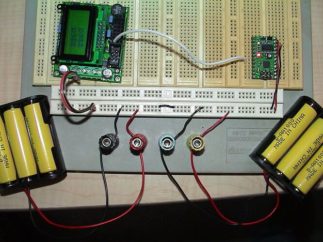
What are you using as your power source/sources? Are these weird characters always the same, and can you take and post a picture of them (I can try to duplicate them)? Actually a picture that showed all your wiring connections might help too.

Sorry you’re still having trouble, but at least we have an idea of where the problem is coming from now.

-Adam

Hello.

It’s strange that you get different behavior when using one power source vs two. This would indicate to me that you are not wiring things properly in the case where you’re using two power sources.

In the case where you’re using one power source, I wonder if perhaps the Baby-O is starting to transmit before the Orangutan is ready to receive. One suggestion I’d make is to move the 1-second delay

for(i=0;i<100;i++){ 
         _delay_ms(10); 

to the top of the while(1) loop (before the USART_Trans(‘T’)) and see if that has any effect at all.

- Ben

If I use Ben’s suggestion of moving the delay above While caused both lines of wierd character to scroll.
I have pictures but, can’t figure out how to post them.

To be clear, my suggestion was to move the delay to the top of the while loop (so that it’s still inside the while loop), not above it. I think you can try using something like imageshack or photobucket to host your pictures.

- Ben

Here is how I have it hooked up.

Well first I think I see your separate power problem. The Baby Orangutan has a linear voltage regulator, not a step-up regulator like the LV-168 Orangutan, so it needs between 5 and 10 volts to operate properly. If those are alkaline batteries you’ll need at least a fourth one, and if they’re NiCd or NiMH rechargables you’ll want five at least (Don’t put more batteries on the LV-168 though!).

Low power to the Baby-O might be the entire problem, but if not, there could also still be a baud-rate mismatch. Looking back I see now that you said it, but somehow it didn’t register in my mind that you have an LV-168 Orangutan! The Orangutan-side code I wrote is meant to run at 8Mhz, on the ATMega168’s internal clock (like on the original Orangutans). I don’t have one myself (yet) but I think the LV-168 comes with an external 20MHz oscillator built into the board, and it might come with the fuse set to use it (Ben, or anyone else, can you confirm this? The dotted line around it in the schematic makes me a little unsure.)

Anyway, I don’t have my Orangutans in front of me right now to try to reproduce the Katakana on your screen, but take a look at the fuse settings on your Orangutan (LV) again. Of course, don’t check any of the Ext. Crystal fuses yourself until we hear back from someone at Pololu that there is for sure an external oscillator already hooked up. If one of the Ext. Crystal fuses is already checked, try changing the first line of the Orangutan-code from:
#define F_CPU 8000000//CPU clock
to:
#define F_CPU 20000000//CPU clock

This doesn’t change the actual clock speed at all, but it does change the way the serial hardware calculates its baud rate based on the clock speed it expects.

So, I hope this does it. Sorry if I lead you astray.

-Adam