
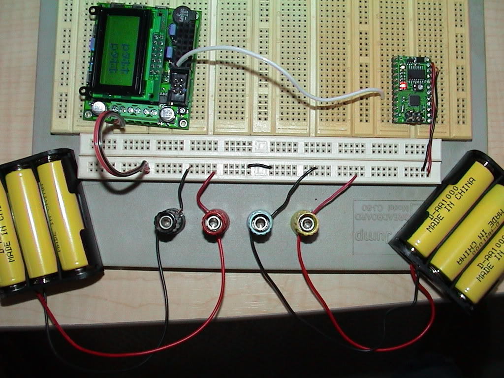
Here is how I have it hooked up.
Well first I think I see your separate power problem. The Baby Orangutan has a linear voltage regulator, not a step-up regulator like the LV-168 Orangutan, so it needs between 5 and 10 volts to operate properly. If those are alkaline batteries you’ll need at least a fourth one, and if they’re NiCd or NiMH rechargables you’ll want five at least (Don’t put more batteries on the LV-168 though!).
Low power to the Baby-O might be the entire problem, but if not, there could also still be a baud-rate mismatch. Looking back I see now that you said it, but somehow it didn’t register in my mind that you have an LV-168 Orangutan! The Orangutan-side code I wrote is meant to run at 8Mhz, on the ATMega168’s internal clock (like on the original Orangutans). I don’t have one myself (yet) but I think the LV-168 comes with an external 20MHz oscillator built into the board, and it might come with the fuse set to use it (Ben, or anyone else, can you confirm this? The dotted line around it in the schematic makes me a little unsure.)
Anyway, I don’t have my Orangutans in front of me right now to try to reproduce the Katakana on your screen, but take a look at the fuse settings on your Orangutan (LV) again. Of course, don’t check any of the Ext. Crystal fuses yourself until we hear back from someone at Pololu that there is for sure an external oscillator already hooked up. If one of the Ext. Crystal fuses is already checked, try changing the first line of the Orangutan-code from:
#define F_CPU 8000000//CPU clock
to:
#define F_CPU 20000000//CPU clock
This doesn’t change the actual clock speed at all, but it does change the way the serial hardware calculates its baud rate based on the clock speed it expects.
So, I hope this does it. Sorry if I lead you astray.
-Adam
I changed the power source of the Baby-O to a 9volt and changed the code of the LV-168 to 2000000. Now the LV-168 just stays at Beacon and nothing on the second line. No weird characters. Not Test either.
The LV-168 does have an external 20 MHz oscillator and we configure it to use this external crystal.
I notice you are missing a zero in your clock frequency. Make sure you are setting F_CPU to 20000000 (that’s twenty million: 20,000,000 – you should have seven zeroes).
- Ben
Hurray!!! That was it Ben. I had missed the zero. I now have Test for the first time. Can’t wait to get back to the original project now. Adam I will let you know how it goes.
Thanks so much guys!!!
Tony
That’s great to hear! All you should need to change to go back to the old code (that displayed NSEW) is the F_CPU number in the first line of the Orangutan code (from 8000000 to 20000000).
You might still want to try bringing in the beacon and the radio separately, you could use this code to send “Test” over the radio, and try the NSEW code over the wire.
-Adam
I hooked the radios up. I left the test code in both MCUs. No IR Beacon. I have each radio sharing power from corisponding MCU. Nothing comes across the LCD of the LV-168 unless I touch either antenna of the radio. Then the weird characters show up. That sounds like a ground issue to me, but not sure what to do about it. I hate to give the radios seperate power source. Oh, I also took out the common ground beteen the MCUs. Just to make sure I am still outputting the Test code I put back the common ground and move the wire and still get expected outcome of Test.
Thoughts?
Tony
The transmitter should operate just fine from your 9V battery, but the receiver really wants to run off of 5V. You might try powering it off of one of the 5V I/O power ports of your Orangutan (you’ll need to connect the selection jumper, see the Orangutan LV-168 usage notes). The radio manufacturer doesn’t really specify how much current the receiver needs to run, but the Baby O’s step up regulator can handle 200mA, so it should be enough.
If this doesn’t do it another picture of your breadboard should be worth 1000 words.
-Adam
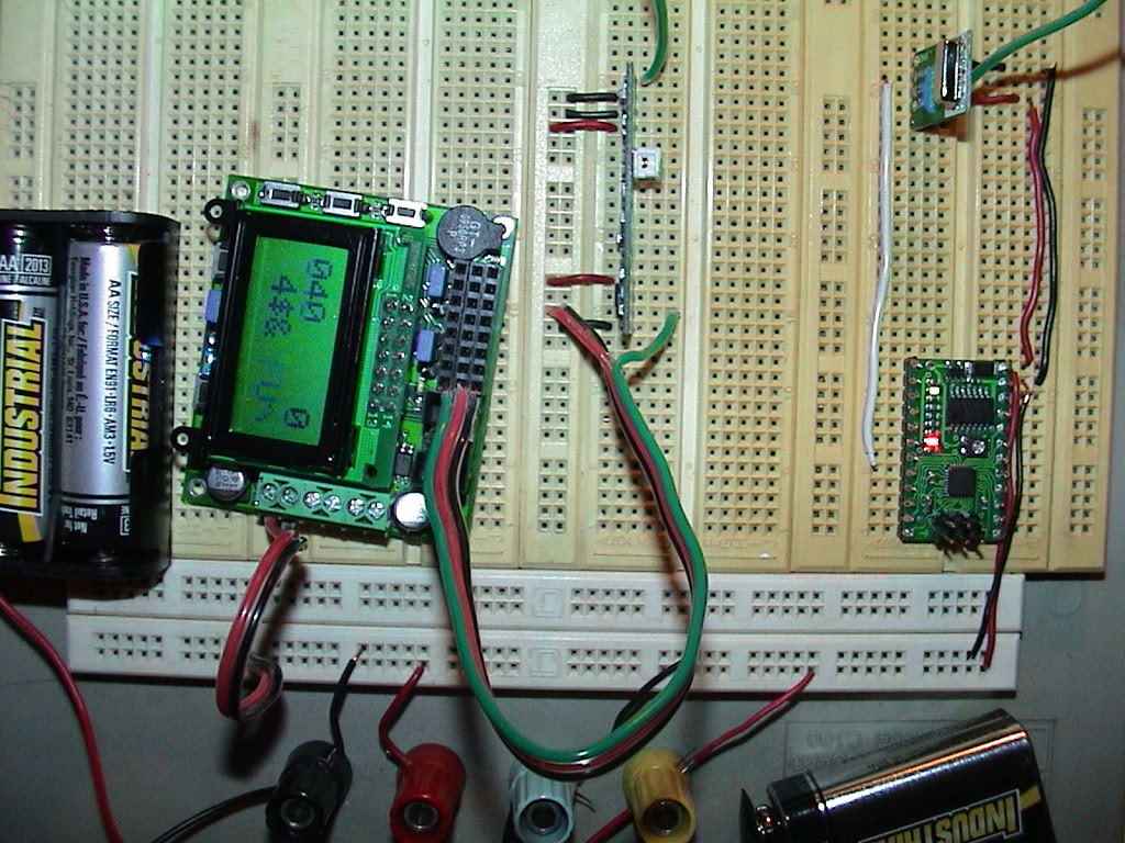
Looks like you have everything wired up correctly. And on further reading, Sparkfun says that the receiver only uses about 3.5mA, so it should be fine running off of 5V from your LV-168 Orangutan.
Reading a little bit about this on the Sparkfun wireless forums, some people have problems with the transmitter overwhelming the receiver when they are placed very close together (i.e. on the same breadboard). First, try getting rid of your antenna wires (you can put them back if you want later, when the devices are a little more separated). You can also reduce the transmitter strength by powering it from the Baby O’s 5V regulator (connect the transmitter VCC pin to the Baby O’s VCC pin, which is unfortunately a little cumbersome to do on a breadboard since you don’t want to short VCC and M1).
I’m also finding posts from a lot of people who are dissatisfied with how sensitive to noise and interference these radios are. I find this very odd, since the Sparkfun product description practically glows about how fantastic and simple a cut-the-cord wireless solution these are. I know you said before you were trying to keep this project cheap, but you may want to think about investing in some better radios, like ones that do internal signal processing and error checking. I’ve used the LPRS easyRadio modules with great success, but they’re also about five times more expensive than these. Anyway, that’s for later. Before even thinking about that you should be able getting some good data flowing between these!
-Adam
Adam,
I tryed connecting the trans. to the VCC of the Baby-O and that did not help. Not sure what made me think of this but I tryed what Ben suggested aways back.
for(i=0;i<100;i++){
         _delay_ms(10);
to the top of the while(1) loop (before the USART_Trans(‘T’)) and see if that has any effect at all.
- Ben
By golly it worked!!
Now for the next part of hooking back up the IR beacons and code for that.
Wish me luck,
Tony
Adam & Ben,
The whole thing works perfectly!
Thanks so much for your consistent help in this project. Top notch support even at some crazy hours. I learned a bunch. This project is not actually for a robot, but I am anxious to start one. I have taken apart an old remote control car that has a good base for starting a robot so I will most likely need help on that project someday.
For now I am off to testing the 3 piece IR Beacon in the real environment, outdoors.
Thanks a million.
Cheers,
-Tony
I’m very glad to hear you were able to get everything working!
- Ben
Hello,
I haven’t been following this conversation that much, but I don’t think the IR beacon will work very well outdoors. Maybe at night.
- Jan
I hoped that would not be the case. Is the problem in the IR trans. or IR receive or both. Is there different sensors I can add to the IR Beacon board to help? Could you offer any advice. I realy like the Pololu IR Beacon set up so I hate to move from it if the outdoors becomes a problem.
-Tony
The IR beacon is based on transmitting IR and comparing the IR reception on the receivers facing in different directions. The LEDs are already set to be very bright to get 20’ range indoors, but if it’s bright enough outside, the receivers just won’t see the transmitters. There’s not much you can do about that, but you can at least try to cover the receivers so that they are not in direct sunlight. Your results will probably vary with the time of day and weather.
- Jan
Jan,
Check out this encloser seller/site. hammondmfg.com/dwg2c.htm
Would the blue or red help.
-Tony
It looks like the red one might help.
- Jan
Hey nexisnet,
wondering if you could spend a minute or two looking at this code. You will see some of it is code you had helped me on. Recall I needed the IR beacon to be wireless and that part works great in this code I am posting. However now I am looking to get the EZ1 to come across wireless and have piced in code that Ben helped me on when I used the EZ1 with ADC.
My Receive code:
#define F_CPU 20000000//CPU clock
#define BAUD 2400//baud rate for UART
#define MYUBRR (F_CPU/16/BAUD-1)//baud rate variable for UART hardware

#include <avr/io.h>
#include <avr/interrupt.h>
#include "device.h"
#include "lcd.h"


unsigned char newBeaconState=0;

ISR(USART_RX_vect){//USART Byte reieved
   newBeaconState=1;
}

void USART_Init(unsigned int ubrr){//Initialize USART hardware & settings for Serial Radio
   UBRR0H=(unsigned char)(ubrr>>8);//set buad rate
   UBRR0L=(unsigned char) ubrr;
   UCSR0B=(1<<RXEN0);//enable reciever
   UCSR0B|=(1<<RXCIE0);//enable recieve complete interrupt
   UCSR0C=(3<<UCSZ00);//Set frame format for 8bit with 1 stop
}

void delay_ms(unsigned int time_ms)  // delay for time_ms milliseconds
{
    while (time_ms--)
        delay_ms(1);  // defined in <util/delay.h>, argument must be < 13
}


int main(){
   lcd_init(); // this function must be called before any other LCD command

   	USART_Init(MYUBRR);//Initialize serial USART
	sei();//enable global interrupts


while (1){         // loop forever

      long sum = 0;
      unsigned int avg;{


           UDR0 |= ( 1 << PC4 );      // start conversion
         while (UDR0&(1<<PC4))      // wait while converting
            ;
         sum += PC4;                     // add in conversion result
      }
      avg = sum >> 9;      // a.k.a. avg = sum / 2^9 = avg / 512
                     //  typically, bitshifting is faster than division


      if(newBeaconState){
         newBeaconState=0;
         lcd_gotoxy(0, 1); // go to the start of LCD line 2


         if(!(UDR0&(1<<PC1))){//east detected, do something
            lcd_string("<--     "); // write a character

         }

         if(!(UDR0&(1<<PC2))){//south detected, do something
            lcd_string("   <>   "); // write a character

         }

         if(!(UDR0&(1<<PC3))){//west detected, do something
            lcd_string("     -->"); // write a character
         }

		 if(!(UDR0&(1<<PC4))){//EZ1 detected, do something
      		lcd_gotoxy(0, 0);
			lcd_string("DIST:");
      		lcd_gotoxy(6, 0);            // go to the start of LCD line 2
      		lcd_int(avg * 4.89 / 117.60);   // display average ADC as an integer
         }

		 else{
            lcd_string("NOSIGNAL"); // write a space
         }

	  }

 }

   return 0;
}
My Transmit code:
#define F_CPU 20000000//CPU clock
#define BAUD 2400//baud rate for UART
#define MYUBRR (F_CPU/16/BAUD-1)//baud rate variable for UART hardware

#include <util/delay.h>
#include <avr/io.h>

void USART_Init(unsigned int ubrr){//Initialize USART hardware & settings for Serial Radio
   UBRR0H=(unsigned char)(ubrr>>8);//set buad rate
   UBRR0L=(unsigned char) ubrr;
   UCSR0B=(1<<TXEN0);//enable transmitter
   UCSR0C=(3<<UCSZ00);//Set frame format for 8bit with 1 stop
}

void USART_Trans (unsigned char data){//Transmit a byte of data over USART
   while(!(UCSR0A&(1<<UDRE0)));//wait for transmition to complete
   UDR0=data;
}

int main(){
   unsigned char i;
   DDRC&=~((1<<PC0)|(1<<PC1)|(1<<PC2)|(1<<PC3)|(1<<PC4));//Configure PortC IO

   USART_Init(MYUBRR);//Initialize serial USART

   while(1){
      for(i=0;i<512;i++){
         _delay_ms(10);

	  USART_Trans(PINC);//Transmit state of PINC

      }
   }

   return 0;
}
Hey Tmapes, the code looks good to me, is it working well?
I’m a little confused though, the sonar ADC is on the receiver side, are you thinking of moving it to the transmitter (baby-o) side?
-Adam